Table of Contents
Advertisement
Quick Links
Advertisement
Table of Contents

Related Manuals for Leonton REG5-2602-2C Series


Summary of Contents for Leonton REG5-2602-2C Series
- Page 1 LEONTON REG5-2602-2C Series (REG5-2602-2C / REG5-2602-2C-T) User Manual...
- Page 2 Disclaimer LEONTON Technologies, Co. Ltd. provides this manual without warranty of any kind, expressed or implied, including but not limited to the implied warranties of merchantability and fitness for a particular purpose.
- Page 3 This is a Class-A product. In a domestic environment this product may cause radio interference in which case the user may be required to take adequate measures. This document is the current official release manual. Please check our website (www.leonton.com) for any updated manual or contact us by e-mail (sales@leonton.com).
-
Page 4: Table Of Contents
Contents Overview ..............................1 Software Features .......................... 1 Hardware Features ......................... 1 Package Contents ........................... 2 Safety Precaution ........................... 2 Hardware Description ..........................4 Physical Dimensions ........................4 Front Panel ............................. 5 Rear Panel ............................5 LED Indicators ..........................5 Ethernet Ports .......................... -
Page 5: Overview
Overview This series is rated IP40 and installation by Rack-Mount. Each unit of this industrial gigabit managed Ethernet switch series has 24*10/100/1000Tx and 2 Gigabit combo ports (2*10/100/1000Tx RJ45 or 2*100/1000 SFP slots), suitable for applications that require high bandwidth and long distance communication. In order to prevent unregulated voltage, this series provides high EFT and ESD protection. -
Page 6: Package Contents
or 2*100/1000 SFP Slots) • Store-and-forward switching architecture • 8K MAC Address Table • Supports 9.6Kbytes Jumbo Frame • 4Mbits memory buffer Power Input ● One power 90VAC~264VAC) with AC socket ● Relay Contact: 24 VDC, 1A resistive Certification • CE/FCC Operating Temperature •... - Page 7 Figure 1.2: Hot Surface Warning Label...
-
Page 8: Hardware Description
Hardware Description Physical Dimensions Figure 2.1, below, shows the physical dimensions of REG5-2602-2C series. (W x D x H) is 440mm x 200mm x 44mm Figure 2.1: REG5-2602-2C Series Physical Dimensions... -
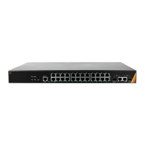
Page 9: Front Panel
Figure 2.2: The Front Panel of REG5-2602-2C Series Rear Panel Figure 2.3, below, shows the rear panel of the REG5-2602-2C series switch that is equipped with one AC power inputs socket (90-264VAC) and one 2-pin terminal block for relay output. - Page 10 Color Description Power input is active Green Power input is inactive Green No event happened FAULT 1. Power input 1 or 2 is inactive 2. Port link-down/Broken ERPS Owner Mode (Ring Master) is ready MASTER Green ERPS Owner Mode is not active ERPS Ring Network is active and works well RING Green...
-
Page 11: Ethernet Ports
Not connected to network Table 2.4: LED Indictors for REG5-2602-2C Series Caution: "PWR" is the abbreviation for "Power", "L" is for "Link", and "A" is for "Activity". Ethernet Ports RJ-45 Ports (Auto MDI/MDIX) The RJ-45 ports are auto-sensing for 10Base-T, 100Base-TX or 1000Base-T devices connections. -
Page 12: Cabling
1000BASE-T RJ-45 Pin Assignments (Table 2.6) Crossover Cable Straight Through Cable Pin Number / Signal Pin Number / Signal Pin Number / Signal Pin Number / Signal 1 / TP0+ 3 / TP1+ 1 / TP0+ 1 / TP1+ 2 / TP0- 6 / TP1- 2 / TP0- 2 / TP1-... - Page 13 Figure 2.7: Transceiver to the SFP Module Figure 2.8: Transceiver Inserted Step 2 Insert the fiber cable of the LC connector into the transceiver as shown below in Figure 2.9. Figure 2.9: LC Connector to the Transceiver To remove the LC connector from the transceiver, please follow the steps shown below: Step 1 Press the upper side of the LC connector from the transceiver and pull it out to release as shown below in Figure 2.3...
-
Page 14: Wiring The Power Input
Figure 2.3: Remove LC Connector Step 2 Push down the metal clasp and pull the transceiver out by the plastic part as shown below in Figure 2.4 Figure 2.4: Pull Out from the SFP Module Wiring the Power Input Caution: Please follow the below steps to insert the power wire. Step 1 Insert the AC power cable into the universal AC socket as shown below in Figure 2.5. -
Page 15: Wiring The Fault Alarm Contact
Wiring the Fault Alarm Contact The fault alarm contact is in the middle of the terminal block connector as the picture shows below in Figure 2.6. By inserting the wires, it will detect the fault status including power failure or port link failure (managed industrial switch only) and form a normally open circuit. An application example for the fault alarm contact is shown below in Figure 2.6. -
Page 16: Mounting Installation
Mounting Installation Rack Mounting This switch can be mounted in a standard 19-inch rack with rack-mount kits. Please follow the step to install rack-mounting switch. Locate one plate to align with the holes on one side of the switch and secure it with the plate screws and then attach the remaining plate to the other side of the switch. -
Page 17: Hardware Installation
Hardware Installation Installation Steps This section will explain how to install REG5-2602-2C series. Caution: This device is intended for use indoor and at altitudes up to 2000 meters. Caution: The device is intended to be installed in an industrial control enclosure and panel Installation Steps Step 1. -
Page 18: Maintenance And Service
Maintenance and Service • If the device requires servicing of any kind, the user is required to disconnect and remove it from its mounting. The initial installation should be done in a way that makes this as convenient as possible. •... -
Page 19: Trouble Shooting
If the power indicator LED does not turn on when the power cord is plugged in, the user may have a problem with the power cord. Check for loose power connections, power losses or surges at the power outlet. ◆ Please contact LEONTON for technical support service, if the problem still cannot be resolved. •...
Need help?
Do you have a question about the REG5-2602-2C Series and is the answer not in the manual?
Questions and answers