Table of Contents
Advertisement
Quick Links
Advertisement
Table of Contents

Related Manuals for Leonton PG5-1600-M12XB-24-67


Summary of Contents for Leonton PG5-1600-M12XB-24-67
- Page 1 ⚫ PG5-1600-M12XB-24-67 ⚫ PG5-1600-M12XB-24-T67...
- Page 2 Disclaimer Leonton Technologies, Co. Ltd. provides this manual without warranty of any kind, expressed or implied, including but not limited to the implied warranties of merchantability and fitness for a particular purpose.
- Page 3 Ceci est un produit de classe A. Dans un environnement domestique, ce produit peut être utilisé en présence d'interférences radio. This document is the current official release manual. Please check our website (www.leonton.com) for any updated manual or contact us by e-mail (sales@leonton.com).
-
Page 4: Table Of Contents
CONTENT OVERVIEW ........................... 1 Key Features ................................. 1 Package Contents ............................... 2 Safety Precaution ................................ 2 HARDWARE DESCRIPTION ...................... 3 Physical Dimensions ..............................3 Front Panel ..................................4 LED Indicators ................................5 Ethernet Ports ................................6 USB Port ..................................7 Console Port ................................. -
Page 5: Overview
OVERVIEW This series is rated IP67 and installation by Wall Mounting. Each unit of this industrial gigabit managed Ethernet switch provided 16*10/100/1000Base-Tx with IEEE 802.3at compliant ports (30W/port), suitable for Ethernet conversion applications. In order to prevent unregulated voltage, this series provides high EFT and ESD protection. This also allows it to function in harsh environments, as well as support power redundancy with a dual power input design with reverse polarity protection. -
Page 6: Package Contents
Package Contents ⚫ 1 - PG5-1600-M12XB-24(-T)-67 - Unit weight: 4.108 kg (9.06 lb), Shipping weight: 4.834 kg (10.66 lb) ⚫ 1 - M12 Protective Cap Set ⚫ 1 - Quick installation guide Safety Precaution Attention If the DC voltage is supplied by an external circuit, please use a protection device on the power supply input. Supply by UL Listed industrial use power. -
Page 7: Hardware Description
HARDWARE DESCRIPTION Physical Dimensions Figure 2.1, below, shows the physical dimensions of PG5-1600-M12XB-24-67 series. (W x H x D) is 295mm x 160mm x 101.3mm Figure 2.1: Physical Dimensions... -
Page 8: Front Panel
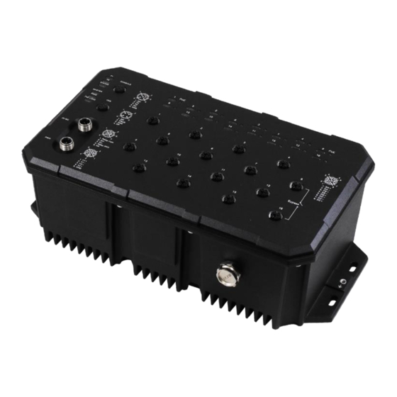
Front Panel The front panel of the PG5-1600-M12XB-24-67 series industrial PoE+ gigabit Managed Ethernet Switch is shown below in Figure 2.2. On the front panel, it provides 16 M12 connectors in a polka dot pattern to ensure easier plugging and safer operation. The LED indicates various status by different colors and shapes of the light. -
Page 9: Led Indicators
LED Indicators There are LED light indicators located on the front panel of the industrial switch that display the power status and network status. Each LED indicator has a different color and has its own specific meaning, see below in Table 2.1. -
Page 10: Ethernet Ports
Ethernet Ports M12 Interface (Auto MDI/MDIX) ⚫ Connection Format: M12 8-Pin X-Coded Female Connector ⚫ Transmission rate: 10/100/1000 Mbit/s Prepare the M12 8-Pin X-Coded Ethernet Port mating cable for Ethernet connection. The M12 X-Coded Ethernet ports are auto-sensing for 10Base-T, 100Base-TX, or 1000Base-T devices connections. Auto MDI/MDIX means that you can connect to another switch or workstation without changing straight through or crossover cabling. -
Page 11: Usb Port
USB Port ⚫ It is a M12 4-Pin A-Coded female connector ⚫ USB Port is for configuration backup / restore ⚫ M12 connector M12 4-Pin A-Coded female Connector Pinouts Function VBUS Console Port ⚫ It is a M12 5-Pin A-Coded female connector ⚫... -
Page 12: Power Inputs
Power Inputs This industrial Ethernet switch provides dual DC power inputs for redundancy through M12 5-pin K-Coded male connector. Prepare the M12 5-pin K-Coded cable for power connection. Table 2.3 shows the pin assignment. M12 5-Pin K-Coded Male Connector Pinouts Function Table 2.3 Connection of Cables... -
Page 13: Relay Contact And Digital Input
Relay Contact and Digital Input The Ethernet switch is equipped a M12 5-Pin A-Coded male connector with a normally closed relay contact for fault alarm and a digital input (DI). The pin assignment of this connector is shown in Table 2.4. M12 5-Pin A-Coded Male Connector Pinouts Function... - Page 14 Digital Input (DI) The digital input is used for monitoring two external events via an external voltage source. When the voltage level on digital input pins changes from high voltage to low voltage, the DI function will be triggered. Table 2.5 is shown a detail specification of the digital input.
-
Page 15: Grounding Note
Grounding Note Grounding and wire routing help limit the effects of noise due to electromagnetic interference (EMI). Run the ground connection from the ground screw to the grounding surface prior to connecting devices. The grounding screw symbol is shown blow in Figure 2.5. Figure 2.5: Grounding screw symbol Caution: Using a shielded cable achieves better electromagnetic compatibility. -
Page 16: Mounting Installation
MOUNTING INSTALLATION Wall Mounting Follow the steps below to mount the industrial Ethernet switch to a wall using the screw holes as shown below in Figure 3.1. Figure 3.1: The Rear Side of the Switch Follow the steps below to learn how to hang the industrial Switch. Step 1. -
Page 17: Hardware Installation
HARDWARE INSTALLATION Installation Steps This section will explain how to install PG5-1600-M12XB-24-67 series. Installation Steps Step 1. Unpack the industrial Ethernet switch from the original packing box. Step 2. To hang the industrial Ethernet switch on a wall, please refer to the Mounting Installation section. - Page 18 Caution: If the equipment is used in a manner not specified by the manufacturer, the protection provided by the equipment may be impaired. Attention: Si l'équipement est utilisé d'une manière non spécifiée par le fabricant, la protection fournie par l'équipement peut être altérée. Caution: The installation that the safety to any system incorporating the equipment is the responsibility of the assembler of the system.
-
Page 19: Trouble Shooting
If the power indicator LED does not turn on when the power cord is plugged in, the user may have a problem with the power cord. Check for loose power connections, power losses or surges at the power outlet. Please contact Leonton for technical support service, if the problem still cannot be resolved. ◆ ●...
Need help?
Do you have a question about the PG5-1600-M12XB-24-67 and is the answer not in the manual?
Questions and answers