Table of Contents
Advertisement
Quick Links
Advertisement
Table of Contents

Related Manuals for Leonton EG2-1002-SFP Series


Summary of Contents for Leonton EG2-1002-SFP Series
- Page 1 LEONTON EG2-1002-SFP Series (EG2-1002-SFP / EG2-1002-SFP-T) User Manual...
- Page 2 Disclaimer Leonton Technologies, Co. Ltd. provides this manual without warranty of any kind, expressed or implied, including but not limited to the implied warranties of merchantability and fitness for a particular purpose.
- Page 3 FCC Notice This equipment has been tested and found to comply with the limits for a Class-A digital device, pursuant to Part 15 of the FCC rules. These limits are designed to provide reasonable protection against harmful interference in a residential installation. This equipment generates, uses, and can radiate radio frequency energy.
- Page 4 Ceci est un produit de classe A. Dans un environnement domestique, ce produit peut être utilisé en présence d'interférences radio. This document is the current official release manual. Please check our website (www.leonton.com) for any updated manual or contact us by e-mail (sales@leonton.com).
-
Page 5: Table Of Contents
Contents Overview ......................................1 Key Features ....................................1 Package Contents..................................2 Safety Precaution ..................................2 Hardware Description ..................................3 Physical Dimensions ................................... 3 Front Panel ..................................... 4 Top View ......................................4 LED Indicators ....................................5 Ethernet Ports ....................................6 Cabling ......................................7 Wiring the Power Inputs ................................ -
Page 6: Overview
Overview This series is rated IP30 and installation by DIN Rail. Each unit of this industrial unmanaged Fast Ethernet switch series has 8*10/100/1000Tx and 2 dual rate (100/1000) SFP slots, suitable for applications that require high bandwidth and long distance communication. In order to prevent unregulated voltage, this series provides high EFT and ESD protection. -
Page 7: Package Contents
Package Contents 1 - EG2-1002-SFP(-T) 2 - Wall mounting brackets and screws Safety Precaution Attention If the DC voltage is supplied by an external circuit, please use a protection device on the power supply input. Supply by UL Listed industrial use power. The industrial Ethernet switch’s hardware specs, ports, cabling information, and wiring installation will be described within this user manual. -
Page 8: Hardware Description
Hardware Description Physical Dimensions Figure 2.1, below, shows the physical dimensions of EG2-1002-SFP series. (W x H x D) is 46mm x 142mm x 99mm Figure 2.1: EG2-1002-SFP Series Physical Dimensions... -
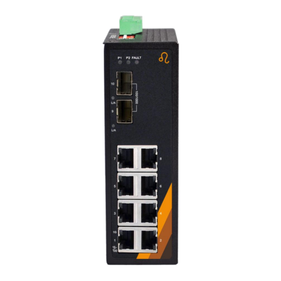
Page 9: Front Panel
Figure 2.2: The Front Panel of EG2-1002-SFP Series Top View Figure 2.3, below, shows the top panel of the EG2-1002-SFP series switch that is equipped with one 6-pin removal terminal block connector for dual DC power inputs (12-48VDC). Figure 2.3: Top Panel View of EG2-1002-SFP Series... -
Page 10: Led Indicators
Not connected to network Green Connected to network, 10/100/1000Mbps Flashing Networking is active Not connected to network LAN Port LINK/ACT Green Connected to network, 10/100Mbps Flashing Networking is active Not connected to network Table 2.1: LED Indictors for EG2-1002-SFP Series... -
Page 11: Ethernet Ports
Ethernet Ports RJ-45 Ports (Auto MDI/MDIX) The RJ-45 ports are auto-sensing for 10Base-T, 100Base-TX or 1000Base-T devices connections. Auto MDI/MDIX means that the switch can connect to another switch or workstation without changing the straight-through or crossover cabling. See the figures as below for straight-through and crossover cabling schematics. -
Page 12: Cabling
Cabling Use the four twisted-pair, category 5e, or the above cabling for RJ-45 port connections. The cable between the switch and the link partner (switch, hub, workstation, etc.) must be less than 100 meters (328 ft.) long. The small form-factor pluggable (SFP) is a compact optical transceiver used in optical communications for both telecommunication and data communication applications. - Page 13 Insert the fiber cable of the LC connector into the transceiver as shown below in Figure Step 2. 2.11. Figure 2.11: LC Connector to the Transceiver To remove the LC connector from the transceiver, please follow the steps shown below: Press the upper side of the LC connector from the transceiver and pull it out to release as Step 1.
-
Page 14: Wiring The Power Inputs
Push down the metal clasp and pull the transceiver out by the plastic part as shown Step 2. below in Figure 2.13 Figure 2.13: Pull Out from the SFP Module Wiring the Power Inputs Please follow the below steps to insert the power wire. Insert the positive and negative wires into the PWR1 (V1+, V1-) and PWR2 (V2+, V2-) Step 1. - Page 15 Figure 2.15: Power Terminal Block Note: Only use copper conductors, 60/75°C, tighten to 5 lbs. The wire gauge for the terminal block should range between 18~20 AWG.
-
Page 16: Wiring The Fault Alarm Contact
Wiring the Fault Alarm Contact The fault alarm contact is in the middle of the terminal block connector as the picture shows below in Figure 2.16. By inserting the wires, it will detect the fault status including power failure or port link failure (managed industrial switch only) and form a normally open circuit. An application example for the fault alarm contact is shown below in Figure 2.16. -
Page 17: Mounting Installation
Mounting Installation DIN-Rail Mounting The DIN-Rail is pre-installed on the industrial Ethernet switch from the factory. If the DIN-Rail is not on the industrial Ethernet switch, please see Figure 3.1 to learn how to install the DIN-Rail on the switch. Figure 3.1: The Rear Side of the Switch and DIN-Rail Bracket Follow the steps below to learn how to hang the industrial Ethernet switch. - Page 18 Figure 3.2: Insert the Switch on the DIN-Rail Lightly pull down the bracket on to the rail as shown below in Figure 3.3. Step 4. Figure 3.3: Stable the Switch on DIN-Rail Check if the bracket is mounted tightly on the rail. Step 5.
-
Page 19: Wall Mounting
Wall Mounting Follow the steps below to mount the industrial Ethernet switch using the wall mounting bracket as shown below in Figure 3.4. Remove the DIN-Rail bracket from the industrial Ethernet switch by loosening the screws. Step 1. Place the wall mounting brackets on the top and bottom of the industrial Ethernet switch. Step 2. -
Page 20: Hardware Installation
Hardware Installation Installation Steps This section will explain how to install EG2-1002-SFP series. Installation Steps Unpack the industrial Ethernet switch from the original packing box. Step 1. Check if the DIN-Rail bracket is screwed on the industrial Ethernet switch. Step 2. -
Page 21: Trouble Shooting
If the power indicator LED does not turn on when the power cord is plugged in, the user may have a problem with the power cord. Check for loose power connections, power losses or surges at the power outlet. Please contact Leonton for technical support service, if the problem still cannot be ◆ resolved.
Need help?
Do you have a question about the EG2-1002-SFP Series and is the answer not in the manual?
Questions and answers