Table of Contents
Advertisement
Quick Links
Advertisement
Table of Contents

Related Manuals for MFJ MFJ-269CPro


Summary of Contents for MFJ MFJ-269CPro
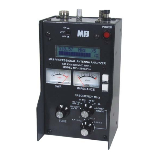
- Page 1 Model MFJ-269CPro INSTRUCTION MANUAL CAUTION: Read All Instructions Before Operating Equipment MFJ ENTERPRISES, INC. 300 Industrial Park Road Starkville, MS 39759 USA Tel: 662-323-5869 Fax: 662-323-6551 COPYRIGHT 2014 MFJ ENTERPRISES, INC. VERSION 1A...
-
Page 2: Table Of Contents
MFJ-269C-Pro Instruction Manual LF/HF/VHF/UHF SWR Analyzer TABLE OF CONTENTS INTRODUCTION YPICAL REQUENCY ANGE CCURACY OTES POWER SOURCES XTERNAL OWER UPPLY NTERNAL ATTERIES ECHARGEABLE ATTERIES “AA” D SING ONVENTIONAL ATTERIES “V ” OLTAGE DISPLAY WARNING “P ” LEEP OWER AVING MAIN MENU AND DISPLAY... - Page 3 MFJ-269C-Pro Instruction Manual LF/HF/VHF/UHF SWR Analyzer ADJUSTING SIMPLE ANTENNAS IPOLES ERTICALS UNING A SIMPLE ANTENNA TESTING AND TUNING STUBS AND TRANSMISSION LINES ESTING TUBS ELOCITY ACTOR OF RANSMISSION INES MPEDANCE OF RANSMISSION INES OR EVERAGE ANTENNAS DJUSTING UNERS DJUSTING MPLIFIER...
-
Page 4: Introduction
(i.e. return loss, reflection coefficient, match efficiency, etc) to any normalized impedance value between 5 and 600 ohms. The MFJ-269C-Pro also functions as a non-precision signal source and frequency counter. Operating frequency extends from 0.53 to 230 MHz in nine overlapping bands with extended SWR measurement from 415 to 520 MHz. - Page 5 MFJ-269C-Pro Instruction Manual LF/HF/VHF/UHF SWR Analyzer The MFJ-269C-Pro is also useful as a non-precision signal source. It provides a relatively pure (harmonics better than -25 dBc) signal of approximately 3 Vpp (~20 mW) into a 50 ohm load. The internal source impedance is 50 ohms. Although not "stabilized", it provides adequate stability for non- critical applications such as alignment of broad-bandwidth filters and circuits.
-
Page 6: Power Sources
Note: Some handheld analyzers display erroneous readings falling outside the reliable measurement range, presenting that data numerically -- as if it were "factual". The MFJ-269C-Pro is designed to avoid such errors by displaying an on-screen warning (Z > 1500) anytime data falls outside the unit's accurate measurement range. - Page 7 MFJ-269C-Pro Instruction Manual LF/HF/VHF/UHF SWR Analyzer The MFJ-269C-Pro has a recessed 2.1 mm power receptacle near the RF connectors. This receptacle is labeled POWER 13.8 VDC. The outside conductor is negative, the center is positive. Inserting a power plug in the POWER 13.8 VDC receptacle disables internal batteries as the analyzer's power source.
-
Page 8: Sleep Mode
15 mA when it is engaged during periods of non-activity. Power-saving is a default setting for the MFJ-269C-Pro unless you defeat it when you turn on the analyzer (instructions below). Normally, the analyzer's processor looks for manual activation of the Mode switch or for any change in Frequency greater than 50 kHz. -
Page 9: Main Menu And Display
LCD window on the left. This switch must be in the "up" or in the Off position unless UHF operation is intended. Note: The following is a description of the basic opening (or default) menu used by the MFJ-269C-Pro. Your analyzer also has an advanced user section (5.0). - Page 10 Momentarily pressing (or tapping) the Mode button after the first working display appears allows you to scroll through all five basic measurement modes provided by the MFJ-269C-Pro. The opening mode is Impedance R & X (resistance and reactance). As each new mode comes up, its title screen appears for about two seconds, and then the companion data screen appears.
- Page 11 Frequency Control The MFJ-269C-Pro tunable RF-oscillator covers an exceptionally wide frequency span, using two rotary band switches for LF/HF/VHF coverage (.53-230 MHz) -- plus an additional pushbutton switch to activate UHF coverage (415-520 MHz) .
-
Page 12: Main (Or Opening) Mode
A basic understanding of antenna theory and transmission line behavior will prove helpful for making the best use of the data provided by your MFJ-259C-Pro. The ARRL Handbook and ARRL Antenna Book provide concise peer-reviewed explanations that should suffice for most applications. When it comes to the finer points of antenna design, there is (unfortunately) a fair amount of misinformation circulating on the web and over the airwaves. - Page 13 6. Adjust Tune (the VFO capacitor) as needed to find your desired test frequency -- or tune until you obtain a minimum SWR reading. Note that the MFJ-269C-Pro also has Advanced antenna-measurement modes that are described in detail in Section-5.0. However, unless you have a strong working knowledge of RF systems, you may find these added modes of limited value.
-
Page 14: Coax Loss
(especially true at VHF and UHF). To measure loss, unterminate the cable at its far end and use the analyzer's Coax Loss mode to check it. 9. Reactance Sign: The MFJ-269C-Pro measures the antenna's reactance (X) and mathematically converts it to a value. Unfortunately, the analyzer's processor can't determine if the reactance it measures is actually inductive (+jX) or capacitive (-jX). -
Page 15: Capacitance
Important Note: Capacitance measurements tend to become inaccurate below 7 ohms and above 650 ohms. If reactance falls into the inaccuracy range, C(X<7), C(X=0), or C(Z>650) will be displayed on the screen as error messages. The MFJ-269C-Pro will not display "data" when the measurement accuracy is questionable (see examples below): Reactance Sign: The MFJ-269C-Pro measures the DUT's reactance (X) and mathematically converts it to a capacitance value (Xc). -
Page 16: Inductance
L(X<7), L(X=0) or L(Z>650) will be displayed. Reactance Sign: The MFJ-269C measures reactance (X) and mathematically converts it to an inductance value X , but the processor can't actually determine if the reactance it measures is inductive or capacitive. -
Page 17: Advanced Operation
MFJ-269C-Pro Instruction Manual LF/HF/VHF/UHF SWR Analyzer Inductance in uH 2. Connect the inductor (DUT) across the Antenna connector using the shortest leads possible, or with the lead length normally used in your working circuit to include stray inductance in the measurement. - Page 18 Accuracy Notes: The MFJ-269C-Pro contains a 50-ohm bridge, with voltage detectors across each bridge leg. A twelve-bit microcontroller processes these voltages and, by applying the proper formulas, displays useful information.
-
Page 19: Advanced 1
The Antenna connector supplies about +7 dBm output into 50 ohms (~ .5 volts RMS), and appears like a 50 ohm source resistance (open circuit voltage ~1 volt RMS). Harmonics are at least 25 dB down over the operating range of the MFJ-269C-Pro. While the VFO is not stabilized, it is useful as a crude signal source. - Page 20 MFJ-269C-Pro Instruction Manual LF/HF/VHF/UHF SWR Analyzer To return to the Main (or Basic) menu, press and hold the Mode and Gate buttons to step through the Advanced-2 and Advanced-3 screens. 5.4.1.1 Magnitude and Phase of Load Impedance Magnitude and Phase of Impedance is the first selection in the Advanced-1 menu, and it comes up automatically upon entering Advanced-1 Mode.
- Page 21 This is a powerful tool used in matching antennas, and the MFJ-269C-Pro places it at your fingertips. By checking a load for both Rp and Rs, you can see if either one is close to the desired resistance. If one resistance value is close to the desired value, adding only one component will match the load by canceling reactance.
- Page 22 Resonance Mode draws attention to reactance, displaying it on the Impedance meter as an analog tuning aid for identifying resonance. In this mode, the MFJ-269C measures and displays Frequency, SWR, Resistance (Rs), and Reactance (Xs). When reactance equals zero in a system that has selectivity, the system is said to be resonant.
- Page 23 5.4.2 UHF Advanced-1 To access the Advanced-1 UHF menus, first set up the MFJ-269C-Pro for UHF operation: 1. Rotate Frequency to UHF-LO or UHF-HI. 2. Press in the UHF band switch located above the LCD display.
- Page 24 After a few seconds, the opening display changes to the data screen (samples below). Note that SWR greater than 5:1 falls beyond the measurement range of the MFJ-269C in UHF mode. The Return Loss and Reflection Coeff mode measures and displays Return Loss in dB and Voltage Reflection Coefficient on the LCD.
-
Page 25: Advanced - 2 M
5.5.1.1 DTF Balanced Lines Line placement is critical when measuring balanced line and the MFJ-269C must run on internal batteries to maintain isolation. Also, you must keep the case a few feet away from other conductors and earth. No wires (other than the balanced line) can be attached. Use the Antenna connector’s shield for one lead and the center pin for the other. - Page 26 MFJ-269C-Pro Instruction Manual LF/HF/VHF/UHF SWR Analyzer 5.5.1.2 DTF Coaxial lines Coaxial line placement is not critical -- you may lay in a pile or coil it on the floor. Use internal batteries or external power to run the analyzer, and place it on any convenient surface (conductive or not). Connect coaxial lines normally, with the shield grounded to the outside of the connector.
- Page 27 MFJ-269C-Pro Instruction Manual LF/HF/VHF/UHF SWR Analyzer 15.814 MHz 1st Xs= 51 Note that 1st is flashing on and off. This display is prompting you to use Tune to find the frequency where the Impedance Meter shows the lowest reading for Xs (as close to Xs=0 as possible). When you find that frequency, press and hold Gate until the flashing 1st on the display stops flashing.
- Page 28 5.5.2 Calculator Functions (direct access) The MFJ-269C-Pro performs calculator functions. These functions may also be accessed from the Distance to Fault modes. Calculator functions: 1. Calculate length in feet of a transmission line or conductor for the number of electrical degrees (up to 359 degrees) of a transmission line or conductor for the velocity factor and length entered and the frequency selected (see section 5.5.2.1).
- Page 29 MFJ-269C-Pro Instruction Manual LF/HF/VHF/UHF SWR Analyzer VELOCITY FACTOR? VF= 0.70 Note: If you know the true electrical length in feet, set Vf to VF=1.0 and enter the Electrical Length in feet. 3. Press Mode, and a display showing Length in Feet and Length in Degrees will appear.
- Page 30 MFJ-269C-Pro Instruction Manual LF/HF/VHF/UHF SWR Analyzer If this mode is entered after using distance to fault (see section 5.5.1), VF and length will be programmed automatically using distance to fault data. The physical or electrical length of the line can also be programmed manually.
- Page 31 MFJ-269C-Pro Instruction Manual LF/HF/VHF/UHF SWR Analyzer 7. To increase line length in degrees, press Gate. To decrease it, press Mode. When the desired length appears, simultaneously press and hold Gate and Mode to lock it in. The display will now change to:...
-
Page 32: Adjusting Simple Antennas
MFJ-269C-Pro Instruction Manual LF/HF/VHF/UHF SWR Analyzer 5.6.2 Coax Loss Please re-read and apply the method presented in section 4.2.2 Coax Loss, before using this advanced function. It explains the loss measurement in detail. Access this mode via the Z Characteristic screen (5.6.1) by pressing Mode. In this mode, Zo flashes in the upper right and Coax Loss appears on the display. -
Page 33: Verticals
Select any mode that indicates SWR, then use the following steps to tune a basic coax-fed antenna: 1. Momentarily short the center and shield to discharge static, then connect to the MFJ-269C-Pro. 2. Adjust the MFJ-269C-Pro VFO to the desired frequency. -
Page 34: Velocity Factor Of Transmission Lines
1/4, etc.). It must be short circuited for all half-wave stub multiples (like 1/2, 1, 1-1/2, etc.). If a balanced line is used, operate the MFJ-269C-Pro from internal batteries and keep its case isolated by a few feet from other conductors or earth. Do not attach any wires (other than the feedline). Use the Antenna connector shield for one lead and the center pin for the other. -
Page 35: Impedance Of Transmission Lines Or Beverage Antennas
(X=). If a balanced line is used, operate the MFJ-269C-Pro only from internal batteries and keep it a few feet away from other conductors or earth. Do not attach any wires (other than the feedline) to the unit. Use the Antenna connector’s shield for one lead and the center pin for the other. -
Page 36: Adjusting Tuners
240,000 is 490. The impedance is 490 ohms. Using a potentiometer or resistor decade box: 1. Connect the MFJ-269C-Pro to one end of the system (in this case you can use a broadband matching transformer). 2. Adjust the frequency and note only the SWR change. -
Page 37: Adjusting Amplifier Matching Networks
4. Turn off the MFJ-269C-Pro and re-connect the transmitter. Adjusting Amplifier Matching Networks The MFJ-269C-Pro can be used to test and adjust RF amplifiers or other matching networks without applying operating voltages. The tubes and other components should be left in position and connected so that stray capacitance is unchanged. -
Page 38: Testing Rf Chokes
Troublesome series-resonance can be detected by installing the choke in the operating location, and connecting only the MFJ-269C-Pro from end-to-end of the choke through a short 50 ohm jumper cable. By slowly sweeping the operating frequency range of choke, dips in impedance identify low impedance series-resonant frequencies. -
Page 39: Technical Assistance
If you have any problem with this unit first check the appropriate section of this manual. If the manual does not reference your problem or your problem is not solved by reading the manual, you may call MFJ Technical Service at 662-323-0549 or the MFJ Factory at 662-323-5869. You will be best helped if you have your unit, manual and all information on your station handy so you can answer any questions the technicians may ask. - Page 40 This warranty is given in lieu of any other warranty expressed or implied. 10. MFJ Enterprises, Inc. reserves the right to make changes or improvements in design or manufacture without incurring any obligation to install such changes upon any of the products previously manufactured.
Need help?
Do you have a question about the MFJ-269CPro and is the answer not in the manual?
Questions and answers