Table of Contents
Advertisement
Quick Links
Advertisement
Table of Contents

Related Manuals for MFJ 226


Summary of Contents for MFJ 226
-
Page 2: Table Of Contents
Firmware version V01R02INTRODUCTION........3 INTRODUCTION ................2 THEORY OF OPERATION..............3 MFJ-226 Technical Specifications ............4 LAYOUT AND CONTROLS ..............5 1. Analyzer Test Port:..............5 2. USB Data Port:...............5 4. Boot Key:................5 5. Arrows (up/down): ..............5 6. Enter Key:................5 7. Return (Exit): ................5 8. Mode ..................5 9. - Page 3 The MFJ-226 is accurately calibrated at the factory and should not need recalibration for initial use. Do not run CALIBRATE with out proper calibration loads.
-
Page 4: Introduction
MFJ-226 Graphical Antenna Impedance Analyzer INTRODUCTION The MFJ-226 is part of the Times Technology Series of analyzers and is a compact single-port Vector Network Analyzer (VNA) that characterizes complex RF loads in 50-Ohm systems with a high degree of accuracy. Packaged for portable use, it's easy to operate under a wide range of test conditions yet delivers many advanced features usually reserved for units costing much more. -
Page 5: Firmware Version V01R02Introduction
MFJ-226 Graphical Antenna Impedance Analyzer Whether you are putting up a simple dipole, building a complex matching network, or characterizing an unknown device, the MFJ-226 delivers the type of data you need to get the job done. A user-friendly menu system provides rapid access to all operating modes and... -
Page 6: Mfj-226 Technical Specifications
Using the Keypad and Menu System, the operator can call up the specific type of data needed for display on the LCD Screen. The MFJ-226 is compact and simple to use, but offers several advanced features that set it apart from may lower-cost analyzers. -
Page 7: Layout And Controls
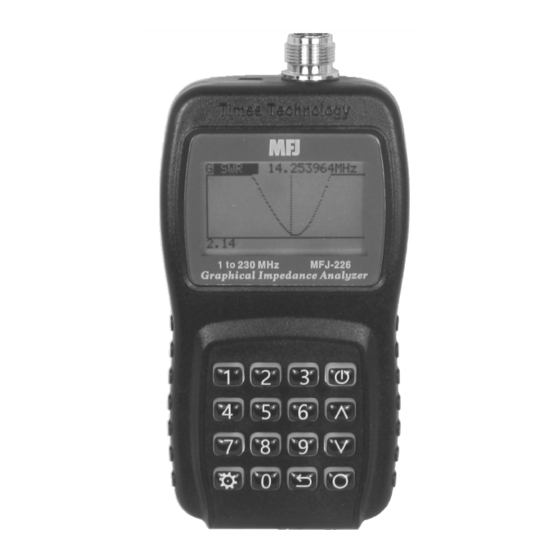
MFJ-226 Graphical Antenna Impedance Analyzer LAYOUT AND CONTROLS MFJ-226 1. Analyzer Test Port: N-Female, accepts N-male for DUTs and calibration loads. 2. USB Data Port: Accepts micro-USB connector, interface with a PC for download. (Not for powering the unit or charging batteries). -
Page 8: Powering The Mfj-226
Abruptly cutting power can disrupt the unit's normal power-down cycle and result in memory loss. The MFJ-226 features a built-in battery indicator that must be set up for the type of battery you intend to use. See the Settings Menu for details. -
Page 9: Backlight
MFJ-226 Graphical Antenna Impedance Analyzer Enter. To go back to the Settings menu, press the Return Arrow. See menu items below: 1. Backlight: Controls screen and keypad illumination. Auto: Turns backlight off after a few seconds to conserve power. Turns backlight on full time. -
Page 10: Entering Single-Frequency Mode
MFJ-226 Graphical Antenna Impedance Analyzer ENTERING SINGLE-FREQUENCY MODE To enter the analyzer's Single-Frequency Mode, go to the Main Menu and select Single Freq using the up/down arrows. Then press Enter. The SWR screen will come up. Screen 1, SWR, Frequency: The opening Single-Frequency screen displays SWR, and Frequency. -
Page 11: Screen 3
MFJ-226 Graphical Antenna Impedance Analyzer Screen 3, Series Impedance: Displays the load's resistive and reactive component as two discrete elements connected in series. Also displays a true reactance sign and the inductive or capacitive value at the test frequency. This screen can also be used to determine the value of a capacitor in pF or inductor in mH at the operating frequency. -
Page 12: Entering Swept Frequency Mode
MFJ-226 Graphical Antenna Impedance Analyzer ENTERING SWEPT FREQUENCY MODE This mode plots seven test parameters over a frequency span of your choice. Local Calibration may be used in this mode for accuracy through transmission line. Standing Wave Ratio (SWR) Impedance Magnitude (Z) -
Page 13: Y Scale
SAVING TEST DATA In addition to four cal-data files, the MFJ-226 has 32 data files available to save plots for later upload onto a PC as CSV files. Save File: To save a plot, use the Up/Down Arrow keys to select one of the 32 file locations and press Enter. -
Page 14: Swept Data Screens
MFJ-226 Graphical Antenna Impedance Analyzer SWEPT DATA SCREENS SWR Screen: Each swept plot is identified in the upper left-hand corner, and the tunable marker frequency appears to the right. Use the Up/Down Arrow keys to step or scroll across the display's frequency range. -
Page 15: Reactance Screen (+X Or -X)
MFJ-226 Graphical Antenna Impedance Analyzer Reactance Screen (+X or -X): The Reactance plot tracks both reactive value and displays sign to accurately identify if the load is capacitive or inductive. The resistive component is also shown. 14.250000 MHZ R = 53.20 X = - 5.32... -
Page 16: Smith Chart Screen
DO NOT UNLOCK the CAL DATA PROTECT except during the Global CALIBRATE procedure. The MFJ-226 is accurately calibrated at the factory and should not need recalibration for initial use. The MFJ-226 uses Open/Short/Load (or OSL) calibration to maintain high accuracy for its Global Calibration -- and for "Local Calibration". -
Page 17: Global Calibration File
Poorly made loads will add errors to the calibration causing the unit to loose accuracy especially in the VHF range. High RF Fields may interfere with antenna measurements. You can check the accuracy with known loads to verify that the MFJ-226 is still calibrated. Global Calibration File All of the MFJ-226 analyzer’s calibration data is stored in flash... -
Page 18: Executing Global Calibration
MFJ-226 Graphical Antenna Impedance Analyzer Executing Global Calibration The analyzer’s Global calibration data is normally locked to ensure it cannot be accidentally erased or overwritten by a Local Cal entry. However, it is a good idea to check the calibration and recalibrate your analyzer if needed periodically as a normal preventive maintenance procedure. -
Page 19: Calibration Load Set
Enter. Upon completion, the new Global Cal will lock in place automatically and the analyzer will be ready to use. The MFJ-226 can be re- calibrated at any time. If you suspect your measurement results may be inaccurate for any reason, a Global recalibration will eliminate the analyzer as the source of the problem. -
Page 20: Using Your Pc To Command The Analyzer
The program is part of the Times Technology Series and can control other analyzers in the series. The driver and PC Host program is posted on the MFJ web site. Be sure to install the program before connecting the analyzer to your PC. -
Page 21: Manual Control Via Computer
To save in CSV format click the Save to File and enter the information in the Save As window. To load data from the MFJ-226 click on the Load from T200 button and select the data file to retrieve. Manual Control via Computer This mode can be used for making custom data capture and control routines. - Page 22 The program will start, indicate the progress, then tell you when it is finished. The MFJ-226 will power off and you can disconnect the cable and close the DOS box. The firmware version can be checked in the SETTINGS INFO...
-
Page 23: Month Limited Warranty
Wired and tested PC board products are covered by this warranty provided only the wired and tested PC board product is returned. Wired and tested PC boards installed in the owner’s cabinet or connected to switches, jacks, or cables, etc. sent to MFJ Enterprises, Inc. will be returned at the owner’s expense unrepaired. - Page 24 MFJ ENTERPRISES, INC. MFJ-226 Manual 300 Industrial Park Road Version 1A 1R02 Starkville, MS 39759...
Need help?
Do you have a question about the 226 and is the answer not in the manual?
Questions and answers