Table of Contents
Advertisement
MFJ-269 Instruction Manual
MFJ-269 SWR HF/VHF ANALYZER
Warning: READ SECTION 2.0 BEFORE ATTEMPTING TO USE THIS PRODUCT!
INTRODUCTION 1.0 DESCRIPTION
MFJ-269 SWR HF/VHF ANALYZER
TABLE OF CONTENTS
Warning: READ SECTION 2.0 BEFORE ATTEMPING TO USE THIS PRODUCT
1.0 INTRODUCTION DESCRIPTION
1.1 Typical Uses............................................................................. ....2
1.2 Frequency Range.............................................................................3
1.3 A Quick Word About Accuracy.......................................................3.
2.0 POWER SOURCES .............................................................................................4
2.1 External Power Supply......................................................................4
2.2 Using Internal Batteries.......................................................5
2.2 Using Rechargeable AA Type Batteries....................................5
2.4 Using conventional AADrycell Batteries.............................................6.
2.5 Blinking "VOLTAGE LOW" display warning.............................10
2.6 "Power Saving Mode" (Sleep mode)....................................................6
3.0 MAIN MENU AND DISPLAY ........... ..............................................................7
3.1 General Connection Guidelines............................................................7
3.2 Power-up Display...............................................................................7.
3.3 Main Mode Descriptions (HF functions Only)......................................8
3.4 UHF Operation.................................................................
4.0 MAIN (or Opening) MODE ....................................................................................10.
4.1 General Connection Guidelines.............................................................10
4.2.1 Antenna sustem SWR............................................11
4.3 UHF Main modes
5.0 ADVANCED OPERATION)....................................................................................16
5.1 Forward.................................................................................................16
5.2 Accesing Advanced modes ................................................................17
5.3 General Connection Guidelines.............................................................17
5.4 Advanced 1........................................................................18
TABLE OF CONTENTS
4.2.2 Coax Loss....................................................13
4.2.3 Capacitance..................................................14
4.2.4 Inductance....................................................15
4.2.5 Frequency Counter.......................................15
4.3.1 Antenna sustem SWR (UHF)...................................
4.3.2 Coax Loss (UHF)................................................
5.4.1 HF/VHF Advanced 1
5.4.1.1 Magnitude and Phase of Load Impedance...........18
5.4.1.2 Series Equivalent Impedance .........................19
5.4.1.3 Paralell Equivalent Impedance........................19
HF/VHF/UHF SWR Analyzer
Advertisement
Chapters
Table of Contents

Subscribe to Our Youtube Channel
Related Manuals for MFJ MFJ-269


Summary of Contents for MFJ MFJ-269
-
Page 1: Table Of Contents
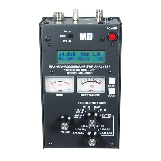
MFJ-269 Instruction Manual HF/VHF/UHF SWR Analyzer MFJ-269 SWR HF/VHF ANALYZER TABLE OF CONTENTS Warning: READ SECTION 2.0 BEFORE ATTEMPTING TO USE THIS PRODUCT! INTRODUCTION 1.0 DESCRIPTION MFJ-269 SWR HF/VHF ANALYZER TABLE OF CONTENTS Warning: READ SECTION 2.0 BEFORE ATTEMPING TO USE THIS PRODUCT 1.0 INTRODUCTION DESCRIPTION... - Page 2 1.0 Description The MFJ-269 RF analyzer is a compact battery powered RF impedance analyzer. This unit combines five basic circuits; a variable oscillator, frequency counter, frequency multiplier, 50 ohm RF bridge, a twelve-bit A-D converter, and microcontroller. This unit performs a wide variety of useful antenna and RF impedance measurements, including coaxial cable loss and electrical distance to an open or short.
-
Page 3: Typical Uses
(harmonics better than -25 dBc) signal of approximately 3 Vpp (approximately 20 milliwatts) into 50 ohm loads. The MFJ-269 internal source impedance is 50 ohms. The MFJ-269 is not a stable generator, but has adequate stability for non-critical applications such as alignment of broad bandwidth filters and circuits. -
Page 4: A Quick Word About Accuracy
Connection lengths both inside and outside the bridge upset readings, especially when impedance is very high or very low. The MFJ-269 minimizes internal problems by using surface mount low capacitance microwave components with nearly zero lead length. Remember any external leads you add, even... -
Page 5: Power Sources
Maximum “sleep mode” and “OFF” voltage (when the power supply is lightly loaded by this unit) is 18 volts. The supply must be reasonably well filtered, the case of the MFJ-269 is connected directly to the negative terminal. The supply must not have a grounded positive lead. -
Page 6: Using Internal Batteries
OFF-ON switch and power connector. This jumper is accessed by removing eight screws along the both sides of the MFJ-269. After the cover mounting screws are removed, remove the entire back cover. The black plastic jumper fits over two of three adjacent pins. It must be properly positioned for the type of battery used (either rechargeable or non-rechargeable). -
Page 7: Blinking "Voltage Low" Display Warning
11 volts. “Power Saving” Mode (sleep mode) The operating current drain of the MFJ-269 is approximately 135 mA for HF operation. Battery life is extended by using an internal "Power Saving” mode. “Sleeping” battery drain is less than 15 mA. -
Page 8: Main Menu And Display
AND ONLY AFTER THE UNIT IS POWERED UP. FOR INFORMATION ON UHF OPERATION, SEE SECTION 3.4 Note: The following is a description of the opening or default menu used by the MFJ-269. This unit also has an advanced user section in section 4.0. -
Page 9: Main Mode Descriptions (Hf Functions Only)
1.) The initial power-up mode is Impedance R&X. When initialized, the following message appears briefly on the front panel display: In this mode, the MFJ-269 LCD (liquid crystal display on front panel) shows frequency in MHz, SWR, the resistive part of load impedance (R=), and the reactive part of load impedance (X=). The IMPEDANCE meter... -
Page 10: Uhf Operation
MFJ-269 Instruction Manual HF/VHF/UHF SWR Analyzer Note: Unless in the advanced modes, this unit displays load impedance in the conventional manner we are all used to seeing. The standard way we describe impedance is a resistance in series with a reactance. -
Page 11: Main (Or Opening) Mode
4.1 General Connection Guidelines a.) The ANTENNA connector (Type “N” female) on top of the MFJ-269 provides the RF measurement output connection. This port is used to measure SWR or perform other RF impedance measurements, with the exception of the Frequency Counter mode. -
Page 12: Hf/Vhf Main Modes
If the antenna does not use a dc grounded element and feed system, momentarily short the antenna lead from shield to center. This prevents static charges from damaging the MFJ-269’s zero bias detector diodes. b.) Immediately connect (in the case of a non-dc grounded feed system) the antenna lead to the MFJ-269 “ANTENNA” connector. - Page 13 MFJ-269 Instruction Manual HF/VHF/UHF SWR Analyzer the antenna and the MFJ-269. If the line is 50 ohms (or the impedance selected in advanced mode 3), this unit will always display the feedline’s true SWR, with the exception of a reduction in SWR present in feedlines having appreciable loss.
-
Page 14: Coax Loss
50 ohms. a.) To measure loss, connect the MFJ-269 to the 50 ohm cable, attenuator, or the transmission line type balun or transformer to be measured. Be sure the distant end of the component tested is not terminated in any resistance or other lossy termination. -
Page 15: Inductance
Adjust the MFJ-269 to a frequency near where you plan to use the component, but be sure the unit does not produce a range warning. “C(Z>1500)” warning indicates the measurement frequency is too low, and “C(X<7)”... -
Page 16: Frequency Counter
“L(Z>1500)” is one warning, and “L(X<7)” is another. “L(X=0)” indicates the inductor appears as a near perfect short to the MFJ-269, and probably indicates frequency is too low or inductance is too small to measure. -
Page 17: Antenna Sustem Swr (Uhf)
MFJ-269 Instruction Manual HF/VHF/UHF SWR Analyzer Never apply dc, or more than 5 volts peak-to-peak voltage to the FREQUENCY COUNTER INPUT BNC jack. In this mode the GATE button controls the frequency counter time window. As a general rule the longer the time window the more accurate the frequency count. -
Page 18: Accesing Advanced Modes
The MFJ-269 contains a 50 ohm bridge, with voltage detectors across each bridge leg. A twelve-bit microcontroller processes these voltages and, by applying the proper formulas, displays useful information. The basic calculations are resistance, reactance, SWR, and complex impedance. -
Page 19: General Connection Guidelines
(open circuit voltage ~1 volt RMS). Harmonics are at least 25 dB down over the operating range of the MFJ-269. While the VFO is not stabilized, it is useful as a crude signal source. The ANTENNA connector is not dc isolated from the load, external voltages will couple directly into internal detectors. -
Page 20: Magnitude And Phase Of Load Impedance
In this mode, the MFJ-269 LCD displays frequency, impedance or Z magnitude (in ohms), and phase angle ( θ ) of impedance. The meters indicate 50 ohm referenced SWR and load Impedance. The maximum impedance limit is set at 1500 ohms, exceeding the limit results in an impedance display of (Z>1500). -
Page 21: Series Equivalent Impedance
Only the 126 ohm resistance remains. This is a powerful tool used in matching antennas. The MFJ-269 places that tool at your fingertips. By checking a load for both Rp and Rs, you can see if either is close to the desired resistance. If one resistance value is close to... -
Page 22: Return Loss And Reflection Coefficient (5.4.1.4)
The Resonance Mode primarily draws attention to reactance, displaying reactance on the IMPEDANCE meter. In this mode, the MFJ-269 measures frequency, SWR, resistance (Rs= ), and reactance (Xs= ). When reactance is zero in a system that has selectivity, the system is said to be resonant. -
Page 23: Match Efficiency (5.4.1.6)
MFJ-269 Instruction Manual HF/VHF/UHF SWR Analyzer This mode functions like other SWR and impedance modes, with the exception the IMPEDANCE meter measures reactance. This allows the operator to easily locate frequencies where system reactance crosses zero. 5.4.1.6 Match Efficiency Match Efficiency is the final measurement mode available in the Advanced 1 menu. This mode is reached (after entering the Advanced 1 menu) by pressing and releasing the MODE button three times. - Page 24 SWR and the impedance meter is disabled. To use this mode, connect the load to be measured to the ANTENNA connector, adjust the frequency to the desired frequency range, and read the results on the MFJ-269 LCD and panel meter displays. 5.4.1.6 Match Efficiency (UHF) Match Efficiency is the second and final measurement mode available in the Advanced 1 UHF menu.
- Page 25 SWR and SWR related functions are displayed. Unfortunately there is now way to cure these problems without causing the MFJ-269 to become unreliable at HF, and any cures would require a calibration fixture to be used at UHF every time a series of measurements are made.
- Page 26 Coaxial lines can lay in a pile or coil on anything, including a floor. Either battery or external power supplies can be used to power the analyzer, and the MFJ-269 can be placed on or near large metallic objects with no ill effects.
- Page 27 MFJ-269 Instruction Manual HF/VHF/UHF SWR Analyzer LOCKED FOR UHF OPERATION ONLY WHEN UHF OPERATION IS DESIRED AND ONLY AFTER THE UNIT IS POWERED UP. FOR INFORMATION ON UHF OPERATION, SEE SECTION 3.4 1.) The first menu that appears is: The GATE button increases the Vf, the MODE button decreases the Vf. Set the Vf to the known Vf of the transmission line.
- Page 28 As with other modes, pressing the MODE button steps back to the beginning. 5.5.2 Calculator Functions (direct access) The MFJ-269 performs calculator functions. These functions can also be accessed from Distance to Fault modes. This functions: 1.) Calculates length in feet of a transmission line or conductor for the number of electrical degrees (up to 359 degrees) of a transmission line or conductor for the velocity factor and length entered and the frequency selected (see 5.5.2.1).
- Page 29 MFJ-269 Instruction Manual HF/VHF/UHF SWR Analyzer This mode tells you length of a line in electrical degrees if you know the physical length and velocity factor. You can also directly measure the electrical length using the distance to fault mode (sec 5.5). This mode is useful for calculating the length in degrees of matching sections and phasing lines.
- Page 30 MFJ-269 Instruction Manual HF/VHF/UHF SWR Analyzer Li n e l e n g th ? l = 1 0 0 .0 ft 6.) To increase line length, press the GATE button. To decrease line length, press the MODE button. When the desired length appears, simultaneously press and hold GATE and MODE buttons.
- Page 31 MFJ-269 Instruction Manual HF/VHF/UHF SWR Analyzer 4.) Press the MODE button again. A display appears showing “Line length in feet” appears and quickly changes 5.) The display will now show line length for the electrical degrees entered (default is 360 degrees) for the velocity factor entered in step 1.
- Page 32 MFJ-269 Instruction Manual HF/VHF/UHF SWR Analyzer This mode is reached by pressing and holding the MODE and GATE buttons until “Advanced 3” appears on the display. This mode allows you to set the SWR reference impedance to values other than 50 ohms, and measure line loss and SWR in systems other than 50 ohms.
- Page 33 MFJ-269 Instruction Manual HF/VHF/UHF SWR Analyzer This mode measures coax loss for the line Zo selected in 5.6.1. it is important that the line is not terminated in any sort or dissipative load when making this measurement. To use this mode, sweep the desired measurement frequency range. Watch the loss reading carefully, and tune for minimum loss.
- Page 34 (like 1/2, 1, 1-1/2, etc.).: 1.) If a balanced line is used, operate the MFJ-269 only from internal batteries. Keep the MFJ-269 a few feet away from other conductors or earth, and do not attach any wires (other than the feedline) to the unit. Use the ANTENNA connector’s shield for one lead and its center pin for the other.
- Page 35 HF/VHF/UHF SWR Analyzer 2.) Coaxial lines can lay in a pile or coil on the floor. Internal or external power can be used, and the MFJ-269 can be placed on or near large metallic objects with no ill effects. Coaxial lines connect normally, with the shield grounded.
- Page 36 2.) Coaxial lines can lay in a pile or coil on the floor. Internal or external power can be used, and the MFJ-269 can be placed on or near large metallic objects with no ill effects. Coaxial lines connect normally, with the shield grounded.
- Page 37 490. The impedance is 490 ohms. Using a potentiometer or resistor decade box: 1. Connect the MFJ-269 to one end of the system (in this case you can use a broadband matching transformer). 2. Adjust the frequency and note only the SWR change.
- Page 38 "ANTENNA" connector on the MFJ-269. The other winding(s) of the transformer is terminated with a low inductance resistor equal to the desired load impedance. The MFJ-269 can then be swept through the desired transformer frequency range. The impedance and bandwidth of the RF transformer can be measured.
- Page 39 Troublesome series-resonances can be detected by installing the choke in the operating location, and connecting only the MFJ-269 from end-to-end of the choke through a short 50 ohm jumper cable. By slowly sweeping the operating frequency range of choke, dips in impedance identify low impedance series-resonant frequencies.
- Page 40 MFJ Technical Service at 601-323-0549 or the MFJ Factory at 601-323-5869. You will be best helped if you have your unit, manual and all information on your station handy so you can answer any questions the technicians may ask.
Need help?
Do you have a question about the MFJ-269 and is the answer not in the manual?
Questions and answers