Table of Contents
Advertisement
Quick Links
Advertisement
Table of Contents

Related Manuals for MFJ MFJ-266C


Summary of Contents for MFJ MFJ-266C
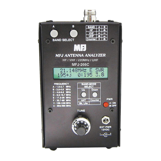
- Page 1 Model MFJ-266C INSTRUCTION MANUAL CAUTION: Read All Instructions Before Operating Equipment MFJ ENTERPRISES, INC. 300 Industrial Park Road Starkville, MS 39759 USA Tel: 662-323-5869 Fax: 662-323-6551 COPYRIGHT 2012 MFJ ENTERPRISES, INC. VERSION 2A...
- Page 2 Customers using this manual should report errors or omissions, recommendations for improvements, or other comments to MFJ Enterprises, 300 Industrial Park Road, Starkville, MS 39759. Phone: (662) 323-5869; FAX: (662) 323-6551. Business hours: M-F 8-4:30 CST.
-
Page 3: Table Of Contents
MFJ-266C HF/VHF/UHF Antenna Analyzer Instruction Manual Contents 1.0 Introduction......................1 2.0 Power Sources......................2 2.1 Internal Batteries....................2 2.2 External Power Supply..................3 3.0 Operating Mode ..................... 3 3.1 Display Backlight....................3 3.2 Main Menu Screen .................... 4 3.3 Frequency Counter Mode (D -> FC) ..............4 3.4 Antenna Analyzer Mode (U ->... -
Page 4: Introduction
Inductance (uH) Relative Field Strength (mV) Frequency (MHz) The MFJ-266C also generates a 2-dBm RF signal that may be used to check receivers, networks, amplifiers, and antenna patterns. Operating range is: 1.5 - 68 MHz in six HF bands VHF:... -
Page 5: Power Sources
MFJ-266C on batteries put the EXT PWR-BAT jumper on the PC board in the BAT position and install the batteries. The MFJ-266C can use either AA cells or a 18650 LI-ion cell to power it on batteries. AA Battery power requires 4 (four) AA-size 1.5-volt alkaline cells. Batteries are installed in a fully encased 4-cell plastic tray mounted inside the analyzer enclosure. -
Page 6: External Power Supply
18650 pack. 2.2 External Power Supply To operate the MFJ-266C on an external power supply open up the unit and move the EXT PWR-BAT jumper from to EXT PWR. The MFJ-266C will not run on external power and batteries at the same time. -
Page 7: Main Menu Screen
Analyzer mode. 3.3 Frequency Counter Mode (D -> FC) In this setup, the MFJ-266C functions as a 1-500 MHz frequency counter. Note that the BAND SELECT switch B must be "up" in the HF position for the counter mode to activate. If switch B is down, an error message will prompt you to change the band setting to HF. -
Page 8: Antenna Analyzer Mode (U -> Ant)
(see Frequency Selection, Section-4). 3.6 L/C Measurement Mode The MFJ-266C may be used to measure the value of unknown capacitors and inductors. To measure L/C values, connect the device to be tested to the antenna jack and follow the procedure outlined below:... -
Page 9: Frequency Selection
MFJ-266C HF/VHF/UHF Antenna Analyzer Instruction Manual 4.0 FREQUENCY SELECTION The MFJ-266C covers the HF region (1.5-71 MHz) in six bands, plus VHF (85-185 MHz) and UHF (300-490 MHz). Tuning and band-selection are electronically switched for high reliability. 4.1 Variable Tuning The TUNE control uses an instrumentation-grade potentiometer with a 10:1 drive reduction to ensure gradual tuning on each band. -
Page 10: Accuracy Limits
17.3 to 39 MHz (17,15,12,10 Meters) 38.7 to 71 MHz (6 Meters) Before moving on to the next section, take time to review the MFJ-266C’s basic set-up procedures. Operation becomes second nature quickly, but should you need it, there’s a supplemental "quick guide" in the back for reference (Section 8.0). -
Page 11: Calibration-Plane Error
(Z = R ± j). By default, the MFJ-266C displays a plus sign (+ j) between the resistive and reactive values, but this sign is merely a placeholder and not a calculated data point. -
Page 12: Antenna Measurements
Standing Wave Ratio (SWR), sometimes referred to as VSWR, is the most widely used format for checking tuning error and impedance mismatch between antennas and radios. The MFJ-266C is calibrated to work on the 50- Ohm impedance standard used by amateur and commercial two-way equipment (Zo=50). -
Page 13: Swr, Bandwidth, And Resonance
MFJ-266C HF/VHF/UHF Antenna Analyzer Instruction Manual (4.) Rotate the Tune knob to find the lowest SWR reading and write it down. (5.) Rotate Tune to either side of minimum SWR and note the 2:1 SWR points. *When testing large ungrounded antenna systems such as HF dipoles, momentarily short the feedline center pin to ground to bleed off static buildup before connecting to the analyzer. -
Page 14: Antenna Matching
If your antenna can’t be tuned or matched to an acceptable SWR level by making physical adjustments, then an external antenna tuner (ATU) should be installed. The MFJ-266C may be used in conjunction with the tuner to make adjustments without the need to transmit test signals over air. Simply connect the analyzer to the tuner input (radio side) through a short patch cable. -
Page 15: Unpredictable Swr
7.0 ADVANCED FUNCTIONS Here are some of the MFJ-266C advance functions. Note that some of these procedures involve connecting component leads to the unit's N connector. For these connections, we suggest making up a very short N-male coaxial pigtail or obtaining a type-N dual binding post adapter to prevent damage the center-contact of the analyzer connector. -
Page 16: Stimulus Generator As A Signal Source
SWR measurements when in Analyzer mode. 7.3 Stimulus Generator as a Signal Source When operated in Analyzer mode, the MFJ-266C generates a +2 dBm CW carrier (2 mW). See section 3.6 for setup procedures. Output will vary slightly, depending on frequency and operating voltage, but typically holds to within 1-2 dB of the rated power level over the analyzer's frequency range. -
Page 17: Measuring Unknown Inductance
Antenna connector. For a 1/4-λ stub, leave the far end open. For a 1/2-λ stub, short the far end. Next: (1.) Set the MFJ-266C to Analyzer mode (Section-3) (2.) Initially, set the Range, Band, and Tune for the desired stub frequency (Section-4) (3.) *Tune down in frequency to find lowest impedance-magnitude reading... -
Page 18: Determining Velocity Factor
7.8 Testing RF Transformers Broadband HF-matching transformers wound for the 12.5 to 200 Ohm range may be tested using the MFJ-266C. Connect the 50-Ohm (primary) side to the analyzer connector using a short pigtail and attach the appropriate resistive load across the secondary side (always use a non-inductive resistor). -
Page 19: Checking Hf Baluns
To check a length of coax cable for impedance error, connect one end to the analyzer and terminate the far end with a precision (non-inductive) 50-Ohm resistive load. Set the MFJ-266C up for analyzer mode and select the VHF tuning range. Rotate Tune across the VHF range while watching the Impedance Magnitude reading. -
Page 20: Quick Guide To Analyzer Controls And Functions
MFJ-266C HF/VHF/UHF Antenna Analyzer Instruction Manual 8.0 QUICK GUIDE TO ANALYZER CONTROLS AND FUNCTIONS Power: Use only 1.5-V Alkaline Batteries. External power must be 10.8-12.5 Vdc, well regulated. Power plug: 2.1-mm, positive (+) to center pin. Power Up: Press PWR, wait for the Main Menu to come up. - Page 21 MFJ-266C HF/VHF/UHF Antenna Analyzer Instruction Manual BAND A HF: 1.5 - 71 MHz VHF: 85-185 MHz UHF: 300-490 MHz Counter X BAND SELECT (2.) Press Up/Down to Select HF Band Press to SCROLL through bands BAND-MODE Tap to STEP through bands SELECT A: 1.5-2.7 MHz...
-
Page 22: Technical Assistance
If you have any problem with this unit first check the appropriate section of this manual. If the manual does not reference your problem or your problem is not solved by reading the manual, you may call MFJ Technical Service at 662-323-0549 or the MFJ Factory at 662-323-5869. -
Page 23: Month Limited Warranty
Wired and tested PC board products are covered by this warranty provided only the wired and tested PC board product is returned. Wired and tested PC boards installed in the owner’s cabinet or connected to switches, jacks, or cables, etc. sent to MFJ Enterprises, Inc. will be returned at the owner’s expense unrepaired. - Page 24 MFJ-266C Manual 300 Industrial Park Road Version 2A Starkville, MS 39759...
Need help?
Do you have a question about the MFJ-266C and is the answer not in the manual?
Questions and answers