Table of Contents
Advertisement
Quick Links
Advertisement
Table of Contents

Related Manuals for MFJ MFJ-266


Summary of Contents for MFJ MFJ-266
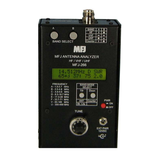
- Page 1 Model MFJ-266 INSTRUCTION MANUAL CAUTION: Read All Instructions Before Operating Equipment MFJ ENTERPRISES, INC. 300 Industrial Park Road Starkville, MS 39759 USA Tel: 662-323-5869 Fax: 662-323-6551 COPYRIGHT 2011 MFJ ENTERPRISES, INC. VERSION 1A...
- Page 2 Customers using this manual should report errors or omissions, recommendations for improvements, or other comments to MFJ Enterprises, 300 Industrial Park Road, Starkville, MS 39759. Phone: (662) 323-5869; FAX: (662) 323-6551. Business hours: M-F 8-4:30 CST.
-
Page 3: Table Of Contents
MFJ-266 HF/VHF/UHF Antenna Analyzer Instruction Manual Contents 1.0 Introduction…………………………………………………………………………………... 1 2.0 Power Sources………………………………………………………………………………… 2 2.1 Internal Batteries…………………………………………………………………….. 2 2.2 External Power Supply………………………………………………………………..2 3.0 Operating Mode……………………………………………………………………………… 3 3.1 Display Backlight…………………………………………………………………….. 3 3.2 Main Menu Screen…………………………………………………………………… 3 3.3 Frequency Counter Mode…………………………………………………………….4 3.4 Antenna Analyzer Mode……………………………………………………………... 4 3.5 RF Signal Source……………………………………………………………………... - Page 4 MFJ-266 HF/VHF/UHF Antenna Analyzer Instruction Manual 7.8 Testing RF Transformers…………………………………………………………… 14 7.9 Checking HF Baluns………………………………………………………………… 15 7.10 Checking Coax Cable…………………………………………………………… 15 8.0 Quick Guide to Analyzer Controls and Functions………………………………………… 16 9.0 Technical Assistance 9.1 Technical Assistance…………………………………………………………………. 17 9.2 Limited Warranty……………………………………………………………………. 19...
-
Page 5: Introduction
Inductance (uH) Relative Field Strength (mV) Frequency (MHz) The MFJ-266 also generates a 2-dBm RF signal that may be used to check receivers, networks, amplifiers, and antenna patterns. Operating range is: 1.5 - 71 MHz in six HF bands VHF: 85-185 MHz continuous coverage UHF: 300-490 MHz continuous coverage A 10:1 vernier drive provides smooth tuning. -
Page 6: Power Sources
MFJ-266 HF/VHF/UHF Antenna Analyzer Instruction Manual 2.0 Power Sources The MFJ-266 may be powered with internal AA batteries or with an external DC supply. To avoid needless damage and ensure top performance, please follow the guidelines below when choosing a voltage source: 2.1 Internal Batteries... -
Page 7: Operating Mode
MFJ-266 HF/VHF/UHF Antenna Analyzer Instruction Manual 2.1 mm Inserting the plug into the power jack automatically disables the internal AA battery pack and switches the analyzer over to the external voltage source. Important Warnings: Reverse polarity or excessive voltage could permanently damage the MFJ-266! To avoid damage: 1. -
Page 8: Frequency Counter Mode
3.3 Frequency Counter Mode (D -> FC) In this setup, the MFJ-266 functions as a 1-500 MHz frequency counter. Note that the BAND SELECT switch B must be "up" in the HF position for the counter mode to activate. If switch B is down, an error message will prompt you to change the band setting to HF. -
Page 9: Rf Signal Source
Impedance Magnitude 3.5 RF Signal Source RF output from the MFJ-266’s built-in stimulus generator is available at the ANT connector in Analyzer mode. This signal is a +2 dBm continuous carrier. When using the analyzer as a signal source, the operating range, band, and frequency are selected in the normal manner and will be displayed on the screen (see Frequency Selection, Section-4). -
Page 10: Frequency Selection
MFJ-266 HF/VHF/UHF Antenna Analyzer Instruction Manual 4.0 Frequency Selection The MFJ-266 covers the HF region (1.5-71 MHz) in six bands, plus VHF (85-185 MHz) and UHF (300-490 MHz). Tuning and band-selection are electronically switched for high reliability. 4.1 Variable Tuning The TUNE control uses an instrumentation-grade potentiometer with a 10:1 drive reduction to ensure gradual tuning on each band. -
Page 11: Accuracy Limits
5.0 Accuracy Limits The MFJ-266 will serve as your “eyes and ears” when working with RF systems, and it can deliver results that rival units costing thousands of dollars. However, all handheld analyzers share certain limitations, and being aware of them will help you to achieve more meaningful results. -
Page 12: Calibration-Plane Error
Most hand-held analyzers (including the MFJ-266) lack the processing capability to calculate the reactance sign for complex impedance (Z = R ± j). By default, the MFJ-266 displays a plus sign (+ j) between the resistive and reactive values, but this sign is merely a placeholder and not a calculated data point. -
Page 13: Antenna Connectors
Instruction Manual 6.1 Antenna Connectors The MFJ-266 uses a type-N female (or NF) connector to ensure reliable signal connectivity up to 500 MHz. It also comes with a SO-239-female to N-male (UHF-NM) adapter for transitioning to popular PL-259 connectors. When purchasing additional adapters, look for N- male rather than UHF transitions. -
Page 14: Antenna Tuning
MFJ-266 HF/VHF/UHF Antenna Analyzer Instruction Manual frequency. The technical definition for resonance is the frequency where inductive and ± capacitive reactance cancels, leaving a purely resistive load ( j = 0). The minimum SWR and resonant frequencies may be close, but they rarely coincide. -
Page 15: Antenna Impedance Readings
Guanella-style balun wound on a ferrite core is recommended. 7.0 Advanced Functions Here are some of the MFJ-266 advance functions. Note that some of these procedures involve connecting component leads to the unit's N connector. For these connections, we suggest making © 2011 MFJ Enterprises, Inc. -
Page 16: Frequency Measurement
SWR measurements when in Analyzer mode. 7.3 Stimulus Generator as a Signal Source When operated in Analyzer mode, the MFJ-266 generates a +2 dBm CW carrier (2 mW). See section 3.6 for setup procedures. Output will vary slightly, depending on frequency and operating voltage, but typically holds to within 1-2 dB of the rated power level over the analyzer's frequency range. -
Page 17: Measuring Unknown Capacitance
Connect one end of the cable to the analyzer's Antenna connector. For a 1/4-λ stub, leave the far end open. For a 1/2-λ stub, short the far end. Next: (1.) Set the MFJ-266 to Analyzer mode (Section-3) (2.) Initially, set the Range, Band, and Tune for the desired stub frequency (Section-4) (3.) *Tune down in frequency to find lowest impedance-magnitude reading (the load is a... -
Page 18: Determining Velocity Factor (Vf)
Broadband HF-matching transformers wound for the 12.5 to 200 Ohm range may be tested using the MFJ-266. Connect the 50-Ohm (primary) side to the analyzer connector using a short pigtail and attach the appropriate resistive load across the secondary side (always use a non-inductive resistor). -
Page 19: Checking Hf Baluns
7.9 Checking HF Baluns A well-designed balun will have low SWR and good balance over its operating range. The MFJ- 266 can test both of these qualities using the setup shown below. Configure the unit to operate in Analyzer mode in the HF range. -
Page 20: Quick Guide To Analyzer Controls And Functions
MFJ-266 HF/VHF/UHF Antenna Analyzer Instruction Manual 8.0 Quick Guide to Analyzer Controls and Functions Power: Use only 1.5-V Alkaline Batteries. External power must be 10.8-12.5 Vdc, well regulated. Power plug: 2.1-mm, positive (+) to center pin. Power Up: Press PWR, wait for the Main Menu to come up. -
Page 21: Technical Assistance
If you have any problem with this unit first check the appropriate section of this manual. If the manual does not reference your problem or your problem is not solved by reading the manual, you may call MFJ Technical Service at 662-323-0549 or the MFJ Factory at 662-323-5869. You will be best helped if you have your unit, manual and all information on your station handy so you can answer any questions the technicians may ask. - Page 22 MFJ-266 HF/VHF/UHF Antenna Analyzer Instruction Manual NOTES © 2011 MFJ Enterprises, Inc.
-
Page 23: Limited Warranty
Any evidence of alteration, erasure, or forgery shall be cause to void any and all warranty terms immediately. 2. MFJ Enterprises, Inc. agrees to repair or replace at MFJ’s option without charge to the original owner any defective product under warranty, provided the product is returned postage prepaid to MFJ Enterprises, Inc. - Page 24 MFJ-266 Manual 300 Industrial Park Road Version 1A Starkville, MS 39759 Printed In U.S.A.
Need help?
Do you have a question about the MFJ-266 and is the answer not in the manual?
Questions and answers