Table of Contents
Advertisement
Quick Links
Advertisement
Table of Contents

Related Manuals for MFJ MFJ-269D


Summary of Contents for MFJ MFJ-269D
-
Page 2: Table Of Contents
MFJ-269D Instruction Manual LF/HF/VHF/UHF SWR Analyzer TABLE OF CONTENTS INTRODUCTION YPICAL REQUENCY ANGE CCURACY OTES POWER SOURCES XTERNAL OWER UPPLY NTERNAL ATTERIES ECHARGEABLE ATTERIES “AA” D SING ONVENTIONAL ATTERIES “V ” OLTAGE DISPLAY WARNING “P ” LEEP OWER AVING MAIN MENU AND DISPLAY... - Page 3 MFJ-269D Instruction Manual LF/HF/VHF/UHF SWR Analyzer TESTING AND TUNING STUBS AND TRANSMISSION LINES ESTING TUBS ELOCITY ACTOR OF RANSMISSION INES MPEDANCE OF RANSMISSION INES OR EVERAGE ANTENNAS DJUSTING UNERS DJUSTING MPLIFIER ATCHING ETWORKS RF T ESTING RANSFORMERS ESTING ALUNS RF C...
-
Page 4: Introduction
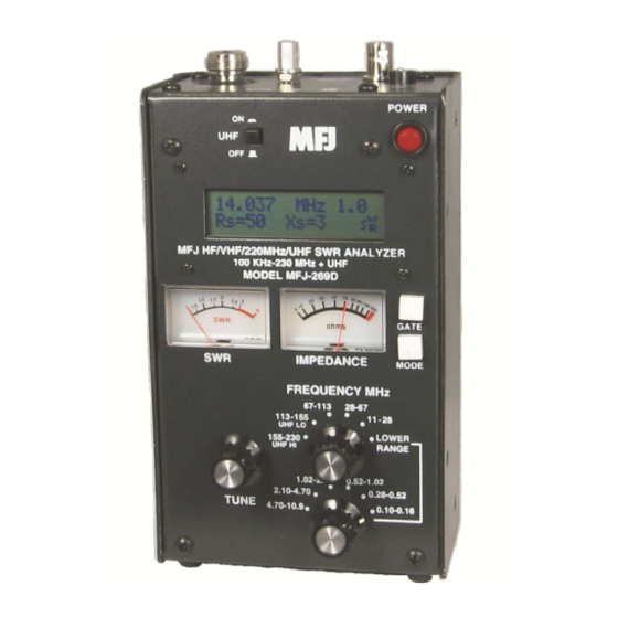
LF/HF/VHF/UHF SWR Analyzer INTRODUCTION The MFJ-269D is a compact battery powered RF impedance analyzer. It combines five basic circuits; a variable oscillator, frequency counter, frequency multiplier, 50-ohm RF bridge, twelve-bit A-D converter, and a microcontroller. Together, these circuits perform a wide variety of useful antenna and RF impedance measurements including coaxial cable loss and electrical distance to an open or short. -
Page 5: Frequency Range
160-meter verticals, these powerful outside signals may couple very efficiently into the analyzer's bridge circuit. Other strong local signals may "get in" as well. To correct the problem, we offer the MFJ- 731 tunable filter, an accessory especially designed to attenuate off-frequency signals. The MFJ-731 permits accurate impedance measurements between 1.8 and 30 MHz with virtually no impact on... -
Page 6: Power Sources
Note: Some handheld analyzers display erroneous readings falling outside the reliable measurement range, presenting that data numerically -- as if it were "factual". The MFJ-269D is designed to avoid such errors by displaying an on-screen warning (Z > 1500) anytime data falls outside the unit's accurate measurement range. -
Page 7: Internal Batteries
WARNING: REVERSE POLARITY OR EXCESSIVE VOLTAGE CAN DAMAGE OR DESTROY THE MFJ-269D. NEVER APPLY MORE THAN 18 VOLTS, NEVER USE AC OR POSITIVE GROUND SUPPLIES! NEVER ADD OR REMOVE BATTERIES WITH AN EXTERNAL POWER SUPPLY CONNECTED TO THIS UNIT, OR WITH THE POWER SWITCH ON. -
Page 8: Voltage Low" Display Warning
Sleep Mode “Power Saving” Typical current drain for the MFJ-269D is around 150 mA for HF operation (250 mA for UHF). Battery operating time is (by default) extended significantly through the use of Sleep Mode. Sleep mode reduces current drain to less than 15 mA when it is engaged during periods of non-activity. -
Page 9: Power-Up Display
LCD window on the left. This switch must be in the "up" or in the Off position unless UHF operation is intended. Note: The following is a description of the basic opening (or default) menu used by the MFJ-269D. Your analyzer also has an advanced user section (5.0). -
Page 10: Frequency Control
Frequency Control The MFJ-269D tunable RF-oscillator covers an exceptionally wide frequency span, using two rotary band switches for LF/HF/VHF coverage (0.10-230 MHz) -- plus an additional pushbutton switch to activate UHF coverage (415-470 MHz) . -
Page 11: Main (Or Opening) Mode
DUT (device under test)! Antenna SWR and Impedance Use the N-Female Antenna connector located on top of the MFJ-269D for all RF measurements (except those using the Frequency Counter mode). Follow the procedure outlined below for measuring SWR:... - Page 12 6. Adjust Tune (the VFO capacitor) as needed to find your desired test frequency -- or tune until you obtain a minimum SWR reading. Note that the MFJ-269D also has Advanced antenna-measurement modes that are described in detail in Section-5.0. However, unless you have a strong working knowledge of RF systems, you may find these added modes of limited value.
-
Page 13: Coax Loss (Function-2)
Coax Loss mode to check it. 9. Reactance Sign: The MFJ-269D measures the antenna's reactance (X) and mathematically converts it to a value. Unfortunately, the analyzer's processor can't determine if the reactance it measures is actually inductive (+jX) or capacitive (-jX). -
Page 14: Capacitance (Function-3)
Important Note: Capacitance measurements tend to become inaccurate below 7 ohms and above 650 ohms. If reactance falls into the inaccuracy range, C(X<7), C(X=0), or C(Z>650) will be displayed on the screen as error messages. The MFJ-269D will not display "data" when the measurement accuracy is questionable (see examples below): Reactance Sign: The MFJ-269D measures the DUT's reactance (X) and mathematically converts it to a capacitance value (Xc). -
Page 15: Inductance (Function-4)
L(X<7), L(X=0) or L(Z>650) will be displayed. Reactance Sign: The MFJ-269D measures reactance (X) and mathematically converts it to an inductance value X , but the processor can't actually determine if the reactance it measures is inductive or capacitive. -
Page 16: Frequency Counter (Function-5)
Accuracy Notes: The MFJ-269D contains a 50-ohm bridge, with voltage detectors across each bridge leg. A twelve-bit microcontroller measures these voltages and, by applying the proper formulas, displays useful information. -
Page 17: General Connections
The Antenna connector supplies about +7 dBm output into 50 ohms (~ .5 volts RMS), and appears like a 50 ohm source resistance (open circuit voltage ~1 volt RMS). Harmonics are at least 25 dB down over the operating range of the MFJ-269D. While the VFO is not stabilized, it is useful as a crude signal source. -
Page 18: Advanced -1 Modes
MFJ-269D Instruction Manual LF/HF/VHF/UHF SWR Analyzer Advanced -1 Modes 5.4.1 Advanced 1 (LF/HF/VHF) Advanced-1 Mode measures impedance and SWR functions. To enter Advanced-1, press and hold down the Mode and Gate buttons simultaneously for approximately two seconds. Advanced 1 There are six display functions available within this mode (see list below): Magnitude and phase of load impedance (5.4.1.1) - Page 19 This is a powerful tool used in matching antennas, and the MFJ-269D places it at your fingertips. By checking a load for both Rp and Rs, you can see if either one is close to the desired resistance. If one resistance value is close to the desired value, adding only one component will match the load by canceling reactance.
- Page 20 Resonance Mode draws attention to reactance, displaying it on the Impedance meter as an analog tuning aid for identifying resonance. In this mode, the MFJ-269D measures and displays Frequency, SWR, Resistance (Rs), and Reactance (Xs). When reactance equals zero in a system that has selectivity, the system is said to be resonant.
- Page 21 5.4.2 UHF Advanced-1 To access the Advanced-1 UHF menus, first set up the MFJ-269D for UHF operation: 1. Rotate Frequency to 155-230 / UHF. 2. Press in the UHF band switch located above the LCD display.
- Page 22 After a few seconds, the opening display changes to the data screen (samples below). Note that SWR greater than 5:1 falls beyond the measurement range of the MFJ-269D in UHF mode. The Return Loss and Reflection Coeff mode measures and displays Return Loss in dB and Voltage Reflection Coefficient on the LCD.
-
Page 23: Advanced- 2 Modes
5.5.1.1 DTF Balanced Lines Line placement is critical when measuring balanced line and the MFJ-269D must run on internal batteries to maintain isolation. Also, you must keep the case a few feet away from other conductors and earth. No wires (other than the balanced line) can be attached. Use the Antenna connector’s shield for one lead and the center pin for the other. - Page 24 MFJ-269D Instruction Manual LF/HF/VHF/UHF SWR Analyzer 5.5.1.3 DTF Antenna Length To measure the electrical length of wire antennas (longwires, dipoles, Beverages), connect through a good broadband matching transformer -- or by connecting directly to the analyzer's Antenna port. To ensure accuracy, avoid using any appreciable lengths of feedline (more than 1/32 wl) between the analyzer and the antenna.
- Page 25 If a different wavelength is required, see section 5.5.3.2. As with other modes, pressing the Mode button steps back to the beginning. 5.5.2 Calculator Functions (direct access) The MFJ-269D performs calculator functions. These functions may also be accessed from the Distance to Fault modes. Calculator functions:...
- Page 26 MFJ-269D Instruction Manual LF/HF/VHF/UHF SWR Analyzer 1. Calculate length in feet of a transmission line or conductor for the number of electrical degrees (up to 359 degrees) of a transmission line or conductor for the velocity factor and length entered and the frequency selected (see section 5.5.2.1).
- Page 27 MFJ-269D Instruction Manual LF/HF/VHF/UHF SWR Analyzer 5. Pressing Mode again takes the display to section 5.5.3.2. Pressing Gate takes the display to a Line Length adjustment function. Line length ? l = 100.0 ft 6. To increase line length, press the Gate. To decrease line length, press Mode. When the desired length appears, simultaneously press and hold Gate and Mode to lock it in.
-
Page 28: Advanced 3 (Lf/Hf/Vhf Only)
MFJ-269D Instruction Manual LF/HF/VHF/UHF SWR Analyzer 4. Press Mode again. The Line Length in Feet screen appears: 5. It then quickly changes to the data screen showing Line Length for the electrical degrees entered (default is 360 degrees) for the velocity factor entered in step 1. Adjust Frequency, and the analyzer will recalculate the correct length for any frequency desired (sample screen): 6. -
Page 29: Adjusting Simple Antennas
MFJ-269D Instruction Manual LF/HF/VHF/UHF SWR Analyzer 3. The small flashing SWR symbol on the lower left means the on-screen reading is referenced to a new Zo (see screen below). The meter, however, continues to indicate SWR normalized to 50-ohms. 4. Pressing Gate (by itself) changes the function back to the Zo setup mode. Pressing the Mode by itself changes the measurement mode to Coax Loss (see 5.6.2 below):... -
Page 30: Verticals
1/4, etc.). It must be short circuited for all half-wave stub multiples (like 1/2, 1, 1-1/2, etc.). If a balanced line is used, operate the MFJ-269D from internal batteries and keep its case isolated by a few feet from other conductors or earth. Do not attach any wires (other than the feedline). Use the Antenna connector shield for one lead and the center pin for the other. - Page 31 Fault mode in Advanced-2 (see section 5.5). If balanced line is used, operate the MFJ-269D only from internal batteries and keep it a few feet away from other conductors or earth. Do not attach any wires (other than the stub) to the unit. Use the Antenna port shield for one lead and the center pin for the other.
- Page 32 (X=). If a balanced line is used, operate the MFJ-269D only from internal batteries and keep it a few feet away from other conductors or earth. Do not attach any wires (other than the feedline) to the unit. Use the Antenna connector’s shield for one lead and the center pin for the other.
- Page 33 4. Turn off the MFJ-269D and re-connect the transmitter. Adjusting Amplifier Matching Networks The MFJ-269D can be used to test and adjust RF amplifiers or other matching networks without applying operating voltages. The tubes and other components should be left in position and connected so that stray capacitance is unchanged.
- Page 34 Troublesome series-resonance can be detected by installing the choke in the operating location, and connecting only the MFJ-269D from end-to-end of the choke through a short 50 ohm jumper cable. By slowly sweeping the operating frequency range of choke, dips in impedance identify low impedance series-resonant frequencies.
- Page 35 If you have any problem with this unit first check the appropriate section of this manual. If the manual does not reference your problem or your problem is not solved by reading the manual, you may call MFJ Technical Service at 662-323-0549 or the MFJ Factory at 662-323-5869. You will be best helped if you have your unit, manual and all information on your station handy so you can answer any questions the technicians may ask.
- Page 36 MFJ Enterprises, Inc. warrants to the original owner of this product, if manufactured by MFJ Enterprises, Inc. and purchased from an authorized dealer or directly from MFJ Enterprises, Inc. to be free from defects in material and workmanship for a period of 12 months from date of purchase provided the following terms of this warranty are satisfied.
Need help?
Do you have a question about the MFJ-269D and is the answer not in the manual?
Questions and answers