Advertisement
Description
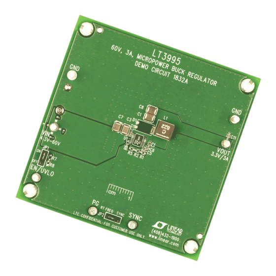
Demonstration circuit 1832A is a monolithic step-down
DC/DC switching regulator featuring the LT3995. The
LT3995 is a compact, high efficiency monolithic step-down
switching regulator that consumes only 2.7μA of quiescent
current. The demo circuit is designed for 3.3V, 3A output
from a 4.3V to 60V input. The switching frequency can be
programmed either via oscillator resistor or external clock
up to 2MHz. To synchronize to an external clock, move
JP2 to SYNC and apply the external clock to the SYNC
turret. The RT resistor (R5) should be chosen to set the
LT3995 internal switching frequency at least 20% below
the lowest synchronization input frequency.
Low ripple Burst Mode
®
ciency at the light load while keeping the output ripple
below 15mV. The SYNC pin on the demo board is grounded
by default by setting JP2 at RT FREQ for low ripple
Burst Mode operation. Figure 1 shows the demo board
efficiency at 12V input voltage.
The LT3995 is in shutdown when the EN pin is low and
active when the pin is high. The threshold of the EN pin
is accurate at 1.02V with 60mV of hysteresis. Users can
populate R7 and R8 to provide a programmable under
90
85
80
75
70
65
60
55
50
45
40
0
0.5
1
LOAD CURRENT (A)
Figure 1. LT3995 Efficiency vs Load Current,
12V
to 3.3V
Efficiency
IN
OUT
operation increases the effi-
1.5
2
2.5
3
dc1832a F01
DEMO MANUAL DC1832A
60V, 3A, 2MHz Step-Down
Switching Regulator with
2.7µA Quiescent Current
voltage lockout. A low dropout voltage of 500mV is main-
tained when the input voltage drops below the programmed
output voltage. During a short-circuit fault, the LT3995
has current limit foldback to limit the power dissipation.
The demo board has an EMI filter installed. The EMI
performance of the demo board at 12V input voltage is
shown on Figure 2. The limit in Figure 2 is EN55022 Class
B. The figure shows the circuit passes the test with a wide
margin. To use the EMI filter, the input should be tied to
VEMI not V
.
IN
The LT3995 data sheet gives a complete description of
the part, operation and application information. The data
sheet must be read in conjunction with this demo manual
for demo circuit 1832A. The LT3995 is assembled in a 16-
lead plastic MSOP package with an exposed pad for low
thermal resistance. Proper board layout is essential for
both proper operation and maximum thermal performance.
See the data sheet sections for details.
Design files for this circuit board are available at
http://www.linear.com/demo
L, LT, LTC, LTM, Linear Technology, the Linear logo and Burst Mode are registered
trademarks of Linear Technology Corporation. All other trademarks are the property of their
respective owners.
70
TRACE 1 PASS
60
50
40
30
20
10
0
–10
–20
–30
START 150kHz
RES BW (CISPR) 9kHz
Figure 2. LT3995 Demo Board EMI Performance
(Switching Frequency = 300kHz, V
LT3995
VBW 62kHz
STOP 30.00 MHz
SWEEP 717ms (6637pts)
dc1832a F02
= 12V)
IN
dc1832af
1
Advertisement
Table of Contents

Related Manuals for Linear LT3995


Summary of Contents for Linear LT3995
- Page 1 1.02V with 60mV of hysteresis. Users can L, LT, LTC, LTM, Linear Technology, the Linear logo and Burst Mode are registered populate R7 and R8 to provide a programmable under trademarks of Linear Technology Corporation. All other trademarks are the property of their respective owners.
- Page 2 Demonstration circuit 1832A is easy to set up to evalu- 4. With power off, connect load from V to GND. ate the performance of the LT3995. Refer to Figure 3 5. Turn on the power at the input. for proper measurement equipment setup and use the 6.
- Page 3 DEMO MANUAL DC1832A Quick start proceDure Figure 3. Proper Measurement Equipment Setup Figure 4. Measuring Input or Output Ripple dc1832af...
-
Page 4: Parts List
RES., CHIP, 182k, 1/16W, 1%, 0402 NIC, NRC04F1823TRF RES., CHIP, 200k, 1/16W, 1%, 0402 NIC, NRC04F2003TRF I.C., LT3995EMSE, MSE16 LINEAR TECHNOLOGY, LT3995EMSE Additional Demo Board Circuit Components CAP., ALUM., 100µF, 100V, 10% SUN ELECT, 100CE100KXT C9, C10 CAP., X7R, 2.2µF, 100V, 10%, 1210 TDK, C3225X7R2A225M CAP., HVP SERIES, 33µF, 63V, 20%... - Page 5 Information furnished by Linear Technology Corporation is believed to be accurate and reliable. However, no responsibility is assumed for its use. Linear Technology Corporation makes no representa- tion that the interconnection of its circuits as described herein will not infringe on existing patent rights.
- Page 6 Linear Technology Corporation (LTC) provides the enclosed product(s) under the following AS IS conditions: This demonstration board (DEMO BOARD) kit being sold or provided by Linear Technology is intended for use for ENGINEERING DEVELOPMENT OR EVALUATION PURPOSES ONLY and is not provided by LTC for commercial use. As such, the DEMO BOARD herein may not be complete in terms of required design-, marketing-, and/or manufacturing-related protective considerations, including but not limited to product safety measures typically found in finished commercial goods.
Need help?
Do you have a question about the LT3995 and is the answer not in the manual?
Questions and answers