Aurora VLX-TCW2H-C User Manual
Hide thumbs
Also See for VLX-TCW2H-C:
- User manual (74 pages) ,
- Product manual (26 pages) ,
- User manual (62 pages)

Related Manuals for Aurora VLX-TCW2H-C


Summary of Contents for Aurora VLX-TCW2H-C
- Page 1 USERS GUIDE VLX Series VLX-TC1-C ● VLX-TCW2H-C ● VLX-TCW2V-C 1GbE Visual Lossless Low Latency AV over IP Distribution VLX-TCW2V-C VLX-TCW2H-C VLX-TC1-C Manual Number: 181008 Firmware Rev: 3.18.0 or Higher...
- Page 2 ⚫ Power outlet: To prevent electric shock, be sure the electrical plug used on the product power cord matches the electrical outlet used to supply power to the Aurora product. Use only the power adapter and power connection cables designed for this unit.
-
Page 3: Table Of Contents
VLX-TC1-C Front ..........................11 VLX-TC1-C Rear..........................13 VLX-TCW2H-C Front .......................... 14 VLX-TCW2V-C Front .......................... 16 VLX-TCW2H-C & VLX-TCW2V-C Rear ..................... 18 VLX-TC1-C Dante Option Slot ......................19 VLX-TCW2 Wall Plate Additional Button & LED Functions ..............19 UNDERSTANDING THE BASICS ....................20 Direct Connection with No Ethernet Switch .................. - Page 4 User Guide System Tab ..............................26 Network Tab..............................31 Functions Tab ..............................32 Remote Tab ..............................33 Management Tab ............................. 34 Preview Tab ..............................35 Decoder Mode Web Pages ......................... 36 System Tab ..............................36 Videowall Tab ..............................41 Network Tab..............................43 Functions Tab ..............................
- Page 5 User Guide APPENDIX 7 Warranty ......................67...
-
Page 6: Package Contents
• 1 qty VLX-TCW2V-C 1G RJ-45 Copper Tranceiver Unit with VGA and HDMI inputs VLX-TCW2H-C • 1 qty VLX-TCW2H-C 1G RJ-45 Copper Tranceiver Unit with Two HDMI Inputs Power supplies are sold separately. Note: Go to www.auroramm.com for latest manual and firmware. -
Page 7: Optional Accessories
OPTIONAL ACCESSORIES • VLX-TC1-RK1 (1RU Rack mount holds 2 units) Includes 4 Rails and 1 Blank • VLX-TC1-RK5 (5RU Rack mount holds 12 units) Includes 24 rails and 4 Blanks • VLX-TC1-BLK (Blank Plate for Rack Mounts) & VLX-TC1-RAIL (For VLX-TC1 use in rack mounts) •... - Page 8 • DXB-8 (8 Button Wall Plate) • PS0081-1 (48V 24 Watt PoE Injector) Available in -US, -AU, - EU, and -UK worldwide models.
- Page 9 • PS0094-2 (48V 25 Watt Wall Supply) Available in -US, -AU, - EU, and -UK worldwide models. • IR Receiver CA0026-1 • IR Emitter CA0061-1 • IR Blaster CA0049-1 • RS-232 Adaptor (3.5mm TRS to FEMALE DB9 2-TX 3-RX) CA0052-F2T3R •...
-
Page 10: Introduction
VLX Series. Documentation Aurora provides many documents to support the VLX series and accessories. Below is a list of the available documents that can be found on the download tab of the VLX products or the customer portal. -
Page 11: Features
128 per source with HDCP, Larger for Non-Encrypted Sources ◆ Videowall with Image Rotation ◆ 1G LAN PoE ◆ 2 HDMI Inputs, 1 HDMI Output (VLX-TC1-C, VLX-TCW2H-C) ◆ 1 VGA/1 HDMI Inputs, 1 HDMI Output (VLX-TCW2V-C) ◆ Line In/Out Stereo ◆... -
Page 12: Vlx-Tc1-C Front
VLX-TC1-C Front LEDs • Power/Status – Power will light green when unit is on or in standby. Status will blink at a normal pace during regular operation and slower pace when in standby. • Encoder/Decoder – Encoder (transmit) or Decoder (receiver) will be lit when set accordingly. - Page 13 Special Functions • Factory Default - Press Power and Menu for 5 seconds. The USB Host LED will blink to indicate factory default and the unit will reboot. • Reboot - Press Power button for 5 seconds. Power LED go off and the board reboots. •...
-
Page 14: Vlx-Tc1-C Rear
VLX-TC1-C Rear Rear From left to right 48VDC 48 Volt DC isolated power input. 10/100/1000Mbps LAN. Can power the unit with PoE from injector or switch. LAN connector LED’s (Rear): Left LED Green = 1G/Good. (1G Req’d for proper operation) •... -
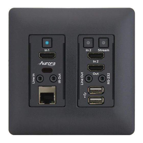
Page 15: Vlx-Tcw2H-C Front
VLX-TCW2H-C Front Buttons • In 1 – Selects HDMI Input 1 (Lights Red, Green, or Blue). • In 2 – Selects HDMI Input 2 (Lights Red, Green, or Blue). • Stream – Selects remote stream assigned when set as decoder (Lights Red, Green, or Blue). - Page 16 Special Functions • Factory Default - Press In1 and In2 button till white LED turns on for a second. Release the switches once the white led turns on, on both the buttons. The unit will reboot automatically after factory default. •...
-
Page 17: Vlx-Tcw2V-C Front
VLX-TCW2V-C Front Buttons • In 1 – Selects VGA (Lights Red, Green, or Blue). • In 2 – Selects HDMI Input 2 (Lights Red, Green, or Blue). • Stream – Selects remote stream assigned when set as decoder (Lights Red, Green, or Blue). - Page 18 Special Functions • Factory Default - Press In1 and In2 button till white LED turns on for a second. Release the switches once the white led turns on, on both the buttons. The unit will reboot automatically after factory default. •...
-
Page 19: Vlx-Tcw2H-C & Vlx-Tcw2V-C Rear
VLX-TCW2H-C & VLX-TCW2V-C Rear Rear • 48VDC – 48 Volt DC isolated power input. • LAN – 10/100/1000Mbps LAN. Can power the unit with PoE from injector or switch. • RS-232 – Serial port pass-through and control up to 115Kbps. Also, has 5V for connection to DXB-8 8 button wall controller. -
Page 20: Vlx-Tc1-C Dante Option Slot
VLX-TC1-C Dante Option Slot • Option Card Slot for Dante option. Note: The MAC address for the Dante option will be on the card label. VLX-TCW2 Wall Plate Additional Button & LED Functions LED Indications • Encoder/Decoder Indication - Blue LED to be lit on Stream button in Encoder Mode. •... -
Page 21: Understanding The Basics
UNDERSTANDING THE BASICS Direct Connection with No Ethernet Switch The VLX Series is designed to automatically tunnel the video, audio, USB, RS-232, and IR if they are connected without an Ethernet switch. 1GbE Ethernet Switch It is important to use a non-blocking IGMP 1GbE switch with IGMP snooping and Jumbo packets. The size of the switch is based on the requirements of the project. -
Page 22: Controlling The Vlx
Non-blocking switch assures full bandwidth is available for all ports as required. Controlling the VLX To simplify control of the VLX, each unit can be controlled via. It can also be controlled from other Aurora control products or 3 party control systems with the available VLX API. -
Page 23: Videowall Capabilities
the better screen can have a benefit. Note scalers do add frame latency and can affect image quality based on the quality of the scaler. This is why it is always ideal to use destinations with similar capabilities for optimal performance. Audio can be impacted just as easily. -
Page 24: Typical Video Network Bandwidth
this application. ● For most of USB devices, the network bandwidth requirement will be almost the same as what it takes on USB bus. Typical Video Network Bandwidth: ● Still frame < 216Kbps ● Web browsing 70~100Mbps (1920x1080) 60fps ● YouTube full screen 21~132Mbps (1920x1080) 60fps ●... -
Page 25: Hardware Installation
1. Connect a 1GbE network switch and make certain IGMP Snooping and Jumbo/MTU Packet features are enabled as per the VLX Series Network Switch Recommendations and Configuration document which can be found on the Aurora website. VLX requires Jumbo/MTU Packet of 8192 or better for full 4K video streaming. -
Page 26: Control Setup
IP Address within the range of what has been set for the units. 2. Launch the windows application IPBaseT Manager available on the Aurora customer portal. 3. The units on the network will populate into the encoder and decoder fields accordingly. -
Page 27: Web Setup Pages
Web Setup Pages Web Setup pages can be accessed by typing in the IP address of the unit followed by /setup (example: 192.168.100.1). You will then be prompted for a password. Default password is admin. Make certain if all the VLX units are already connected to the 1GbE network that each VLX web server has a unique IP Address or there will be communication issues. - Page 28 Version Version reports back the current firmware version. This will help to not only make choices for updating firmware if necessary but by knowing the firmware the user will know the current capabilities that can be expected of the unit.
- Page 29 Update Firmware If updating firmware is necessary, this selection allows a user to select the firmware file and upload to the unit. When the process is done, a notification will appear.
- Page 30 Utilities The selection allows factory defaults, remote rebooting, resetting of EDID as well as the ability to manually enter API commands. The Host ID can also be set up here.
- Page 31 Statistics This selection is very useful when diagnosing the unit as it reveals important information about the unit itself. Everything from MAC, IP, EDID detail, Video Timing and more is all available to help see the state of the unit.
-
Page 32: Network Tab
Network Tab The Network tab allows the setup of the IP address, Subnet, and Gateway. In addition, the mode of point to point (Unicast) or matrixing (Multicast) can be selected under Casting mode. -
Page 33: Functions Tab
Functions Tab The Functions tab has selections pertaining to the Video over IP, Maximum bit Rate which is useful for bandwidth restricted networks, and USB over IP settings. -
Page 34: Remote Tab
Remote Tab The Remote tab has options pertaining to RS232 control. -
Page 35: Management Tab
Management Tab The Management tab manages routing of streaming video sources and mode selection and configuration of serial over IP settings. -
Page 36: Preview Tab
Preview Tab The Preview tab allows you to look at the active video source. -
Page 37: Decoder Mode Web Pages
Decoder Mode Web Pages System Tab The System Tab has 5 selections of Version Info, Updating of Firmware, Utilities, Statistics, and Remote. Hardware Information Shows the Units MAC Address, Serial Number and Mode. - Page 38 Version Version reports back the current firmware version. This will help to not only make choices for updating firmware if necessary but by knowing the firmware the user will know the current capabilities that can be expected of the unit.
- Page 39 Update Firmware If updating firmware is necessary, this selection allows a user to select the firmware file and upload to the unit. When the process is done, a notification will appear.
- Page 40 Utilities The selection allows factory defaults, remote rebooting, resetting of EDID as well as the ability to manually enter API commands.
- Page 41 Statistics This selection is very useful when diagnosing the unit as it reveals important information about the unit itself. Everything from MAC, IP, EDID detail, Video Timing and more is all available to help see the state of the unit.
-
Page 42: Videowall Tab
Videowall Tab The Videowall tab is comprised of the basic and advanced selections. Basic Basic selection has the controls for a user to setup a videowall very easily by entering the active area and the total area. The VLX will figure out the proper slicing of the image based on this information and position/layout. -
Page 44: Network Tab
Network Tab The Network tab allows the setup of the IP address, Subnet, and Gateway. In addition, the mode of point to point (Unicast) or matrixing (Multicast) can be selected under Casting mode. -
Page 45: Functions Tab
Functions Tab The Functions tab has selections pertaining to the Video over IP, Maximum bit Rate which is useful for bandwidth restricted networks, and USB over IP settings. -
Page 46: Remote Tab
Remote Tab The Remote tab allows the selection of the encoder to route to the unit. -
Page 47: Management Tab
Management Tab The Management tab manages routing of streaming video sources and mode selection and configuration of serial over IP settings. -
Page 48: Preview Tab
Preview Tab The Preview tab allows you to look at the active video output. -
Page 49: Applications
APPLICATIONS Example 1: VLX-TCW2 Configured as Transmitter to VLX-TC1 Configured Receiver When the VLX Series is connected point to point, no configuration is required, as the units will auto identify and make a tunnel between both ends for the video, audio, RS-232, IR, USB, and Ethernet. With the copper version a maximum distance of 100m (328ft) can be achieved. -
Page 50: Example 2: Vlx Multi-Room
Example 2: VLX Multi-Room The VLX Series is perfect for multi-room applications with its flexibility. A nearly unlimited number of rooms can share video, audio, data, and control in real-time. The scalability is only limited by the size of the network switch and infrastructure. -
Page 51: Example 3: Matrix - Multiple Vlx To Multiple Vlx
Example 3: Matrix - Multiple VLX to Multiple VLX The VLX can take the place of any typical card cage matrix system, adding flexibility and performance never seen before. Even features like Fast-switch is no longer a premium. -
Page 52: Example 4: Video-Wall
Example 4: Video-Wall The VLX Series is capable of 4K video-walls. Up to 8x8 size can be created with 4K input. -
Page 53: Example 5: Kvm Utilizing Usb 2.0
Example 5: KVM utilizing USB 2.0 Command & Control and NOC centers are perfect for the VLX Series, especially with the USB 2.0 running at a full 50Mbps. With the VLX it is no longer just keyboard and mouse but full USB peripheral routing as well. -
Page 54: Software
SOFTWARE IPBaseT Manager PC Control Tool The IPBaseT Manager is a Windows® based software available at the Aurora customer portal on www.auroramm.com IPBaseT Manager allows a user to control the various capabilities of VLX series products on a network. While the IPBaseT manager is a client software, the IPBaseT Server handles all the communication handling and is the target for all communication. - Page 55 Touch Screen Friendly Layout • Configuration File for Cloning Presets and Connections on Other PCs • Firmware Updating For full detail of the IPBaseT Manager software tool and setup, the manual can be found at the Aurora website www.auroramm.com when it becomes available.
-
Page 56: Connector Pin Definition
CONNECTOR PIN DEFINITION HDMI Pin 1 TMDS Data2+ Pin 8 TMDS Data0 Shield Pin 15 Pin 2 TMDS Data2 Shield Pin 9 TMDS Data0– Pin 16 Pin 3 TMDS Data2– Pin 10 TMDS Clock+ Pin 17 DDC/CEC Ground Pin 4 TMDS Data1+ Pin 11 TMDS Clock Shield Pin 18... -
Page 57: Ir (Infrared)
RS-232 The RS-232 is a 3.5mm TRS connector. Tip is TX (output), ring is RX (input), and Sleeve is ground. To simplify connections Aurora offers pre-molded RS-232 cables in null and none nulled in male and female DB9. IR (Infrared) It will autosense a TS or a TRS connector to determine if an IR emitter (TS) or IR receiver (TRS) is inserted. - Page 58 • IR Receiver CA0026-1 (30kHz – 60kHz) • IR Emitter CA0061-1...
-
Page 59: Appendix 1 Troubleshooting
APPENDIX 1 Troubleshooting It is advisable to make certain all units are using the latest firmware before troubleshooting. Also make sure all network connections are operating are 1G. VLX Web Server is not responding • Make certain every VLX unit has a unique IP Address set for the webserver. Disconnect unit from 1G network and connect PC directly to 1G LAN and check to see if webserver appears in browser. - Page 60 • Check the baud rate of the unit. • Confirm the protocol being utilized with a terminal program. Routing a source to multiple displays is tearing • Check network switch is properly configured for IGMP and supports Jumbo packets. VLX requires Jumbo/MTU Packet of 8192 or better for full 4K video streaming.
-
Page 61: Appendix 2 Firmware Update
You must be signed up to the Customer Portal in order to download firmware with instructions on how to update. APPENDIX 3 Protocol For the latest protocol please go www.auroramm.com You must be signed up to the Customer Portal in order to download VLX protocol. The protocol is only available to authorized Aurora dealers. -
Page 62: Appendix 4 Recommended Cabling
APPENDIX 4 Recommended Cabling The VLX Series has the ability to go the distance. While regular CAT 5e will go 100m (330ft), CAT 6 and 6A can go much further. Below we have tested the following cabling from West Penn and the results of the testing with 4K video. -
Page 63: Appendix 5 Recommended Network Switches
APPENDIX 5 Recommended Network Switches The VLX will work with most non-blocking, IGMP, Jumbo packet 1Gbps network switch. Layer 3 will allow more control, however, Layer 2 will work as well. It is highly recommended to communicate with the representative of the desired network switch brand to confirm configuration and capabilities. -
Page 64: 5.3 Ethernet Switch Configuration
The end results are a noticeably shorter video switching time. Aurora recommends to always enable the FASTLEAVE option when available. 5.3 Ethernet Switch Configuration The following list includes all network switch configuration options that Aurora Engineers have come across so far. Look for these or similar options when configuring your switch. - Page 65 particular switch, then PoE injectors for the remaining ports can be used or the local power supply for the VLX but you may need to disable the detection of the PoE for those ports in the Ethernet switch.
-
Page 66: Appendix 6
APPENDIX 6 Technical Specifications Model Name VLX-TC1 Technical Compression Latency 1.5 Frames (25ms) HDMI Inputs 2 (HDMI 2.0, HDCP2.2) HDMI Outputs 1 (HDMI 2.0, HDCP2.2) Audio Analog Stereo Line In/Out (3.5mm TRS) 1G Copper Ethernet RJ-45 RJ-45 10/100/1000M PoE (PSE) Video Bandwidth 340MHz Video support... - Page 67 Model Name VLX-TCW2 Technical Compression Latency 1.5 Frames (25ms) 1 HDMI 2.0/HDCP2.2 (VLX-TCW2V) HDMI Inputs 2 HDMI 2.0/HDCP2.2 (VLX-TCW2H) HDMI Outputs 1 HDMI 2.0/HDCP2.2 VGA/YPbPr Inputs 1 15 Pin HD Female (VLX-TCW2V) Audio Analog Stereo Line In/Out (3.5mm TRS) 1G Copper Ethernet RJ-45 RJ-45 10/100/1000M PoE (PSE) Video Bandwidth...
- Page 68 Limited 3 Year Warranty Aurora Multimedia Corp. (“Manufacturer”) warrants that this product is free of defects in both materials and workmanship for a period of 3 years as defined herein for parts and labor from date of purchase. This Limited Warranty covers products purchased in the year of 2009 and after.
- Page 69 Aurora Multimedia Corp. 205 Commercial Court Morganville, NJ 07751 Phone: 732-591-5800 Fax: 732-591-6801...
Need help?
Do you have a question about the VLX-TCW2H-C and is the answer not in the manual?
Questions and answers