Aurora VLX Series Configuration Manual
1gbps network switch configurations
Hide thumbs
Also See for VLX Series:
- User manual (74 pages) ,
- User manual (74 pages) ,
- User manual (69 pages)
Table of Contents
Advertisement
Quick Links
NETWORK GUIDE
VLX Series
Network Switch Recommendations & Configuration
IMPORTANT:
This following is presented as informational examples. Switch hardware, software, firmware of these devices may change. Always
consult your switch manufacture to verify compatibility before purchase, and contact the manufacturer for setup and troubleshooting assistance.
ALWAYS pre-stage / test your system for proper configuration and operation prior to site installation.
1Gbps Network Switch Configurations
i
Manual Number: 180101
Advertisement
Table of Contents

Related Manuals for Aurora VLX Series


Summary of Contents for Aurora VLX Series
- Page 1 NETWORK GUIDE VLX Series Network Switch Recommendations & Configuration IMPORTANT: This following is presented as informational examples. Switch hardware, software, firmware of these devices may change. Always consult your switch manufacture to verify compatibility before purchase, and contact the manufacturer for setup and troubleshooting assistance.
-
Page 2: Table Of Contents
Network Guide TABLE OF CONTENTS CABLING ........................... 2 NETWORK SWITCHES ......................3 1.1 Switch Speed ..........................3 1.2 Packets Routing ..........................3 1.3 Ethernet Switch Configuration ......................3 1.4 PoE (Power over Ethernet) ......................4 1.5 Ethernet Switch Models ........................5 1.5 Ethernet Switch Models with Performance Issues ................. -
Page 3: Cabling
Network Guide CABLING The VLX Series has the ability to go the distance. While regular CAT 5e will go 100m (330ft), CAT 6 and 6A can go much further. Below we have tested the following cabling from West Penn and the results of the testing with 4K video. Please note if using a... -
Page 4: Network Switches
The VLX Series requires the switch to be a 1GbE. VLX Series technology is used to transmit visually lossless 8:1 compress video up to 4K along with other AV signals such as audio, USB and control signals. For video alone, it means raw bandwidth of about 850Mbps for 4K and that is just for audio and video. -
Page 5: Poe (Power Over Ethernet)
1.4 PoE (Power over Ethernet) The VLX Series uses around 6 watts of power, however, the PoE is unclassified for up to 12.9 watts (15.4 Watts Total) as the USB on the VLX can supply up to 5 watts. When selecting a PoE switch always make certain the power supply of the PoE switch is proper to the port count (15.4W x qty of ports). -
Page 6: Ethernet Switch Models
1.5 Ethernet Switch Models The following is a list of 1G Ethernet switch models that have been verified to date. Check with Aurora to see if any others may have been added at a later time relative to the manual revision date. -
Page 7: Ethernet Switch Models With Performance Issues
Network Guide 1.5 Ethernet Switch Models with Performance Issues To follow are reported or tested network switches with issues. It is always recommended to check with manufacturer in the event firmware has resolved the reported issues. Cisco SG300 1. The ability to handle multicast request is insufficient. It takes a long time for switches to start forwarding multicast packets to the corresponding ports after receiving IGMP Join messages. -
Page 8: Configurations
Network Guide CONFIGURATIONS Switch Login & Connections Login You must first log onto the switch with administrator right. Follow the switch manufacturer manual to do so. It will also give you the default Admin password. Console Port Some manufacturers use RS-232 / “Console port” for switch configuration and dedicated console cable which is different from a standard Cat X (RJ45) cable. -
Page 9: Cisco C2960 Series
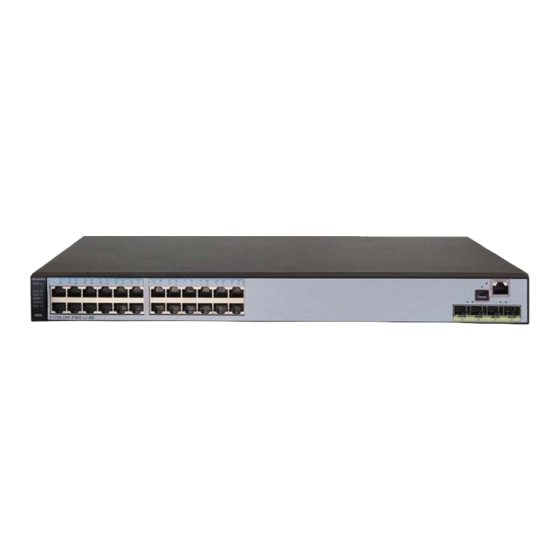
Network Guide Cisco C2960 Series For Cisco C2960 series switches, we would recommend that you use models WS-C2960S-24PS-L, WS-C2960X-24PSQ-L and WS-C2960X-48FPS-L. They can be used for both single switch networking and cascading switch networking. 2.2.1 Basic Operation 2.2.1.1 Logging in to the Switches If you want to configure switches, you need to use special cables and connect them to the switches' dedicated ports. - Page 10 Network Guide connection is successful, switch will not give any prompt. At this moment, press Enter. Switch will give the following prompt. Switch> Switch> The screen capture is as follows. It means that you have successfully logged in to the switch and entered user mode.
- Page 11 Network Guide • Input config terminal to enter global configuration mode. Global configuration mode allows you to change some global configuration. The prompt is as follows. Switch(config)# You can perform the following mode switching operations. • Input end to return privileged mode •...
- Page 12 Network Guide The following screen capture describes the previous steps. Switch reboots. When the following prompt appears, Press RETURN to get started! Press Enter. Switch will give the following prompt. --- System Configuration Dialog --- Enable secret warning ---------------------------------- In order to access the device manager, an enable secret is required If you enter the initial configuration dialog, you will be prompted for the enable secret If you choose not to enter the intial configuration dialog, or if you exit setup without setting the enable secret, please set an enable secret using the following CLI in configuration mode- enable secret 0 <cleartext...
- Page 13 Network Guide The screen capture is as follows. Now, we have successfully reset switch to factory defaults. If some of switch's Ethernet ports are connected to devices using network cables, switch may display their status information during the previous process. You can ignore it. If you forgot password and cannot access privileged mode, you can press and hold MODE button until screen displays the following prompt.
-
Page 14: Manual Configuration
Network Guide The screen capture is as follows. The prompt above means that switch is reset and starts rebooting. Now, you can release MODE button. Wait until switch finishes rebooting and follow the instructions in step 4. 2.2.2 Manual Configuration 2.2.2.1 Configuring Single Switch Networking Based on C2960 series switches' factory defaults, when they are used in single switch networking,... - Page 15 Network Guide It means that you have successfully entered privileged mode. The screen capture is as follows. If no password is required, switch will not ask you to enter password but will directly enter the privileged mode. Enter global configuration mode Enter config terminal.
- Page 16 Network Guide following prompt. Switch(config)#ip igmp snooping querier Switch(config)# The following screen capture describes steps 2-4. Confirm configuration Enter end to return privileged mode. Switch will give the following prompt. Switch(config)#end Switch# *Mar 1 00:39:20.646: %SYS-5-CONFIG_I: Configured from console by console Switch# Input show ip igmp snooping querier detail.
- Page 17 Network Guide Continue to input show ip igmp snooping detail to view IGMP Snooping detail. Switch#show ip igmp snooping detail Global IGMP Snooping configuration: ------------------------------------------- IGMP snooping : Enabled Vlan 1: -------- IGMP snooping : Enabled IGMPv2 immediate leave : Enabled The screen capture is as follows.
- Page 18 Network Guide Save configuration After confirming correct configuration, input write to save the current configuration. Switch will display the following prompt. Switch#write Building configuration... [OK] The screen capture is as follows. Now, it has successfully saved configuration used in single switch networking. Switch will run this IMPORTANT: This following is presented as informational examples.
- Page 19 Network Guide configuration for the next startup. 2.2.2.2 Configuring Core Switches Based on C2960 series switches' factory defaults, when they are used as core switches, only IGMP Querier function needs to be enabled. Perform the following operations after they are reset. Enter privileged mode In user mode input enable.
- Page 20 Network Guide Enter configuration commands, one per line. End with CNTL/Z. Switch(config)# It means that you have successfully entered global configuration mode. Enable IGMP Querier Input ip igmp snooping querier address 192.168.22.222 to assign an IP address for IGMP Querier. Switch will give the following prompt. Switch(config)#ip igmp snooping querier address 192.168.22.222 Switch(config)# Input ip igmp snooping querier to enable IGMP Querier.
- Page 21 Network Guide Confirm configuration Input end to return privileged mode. Switch will give the following prompt. Switch(config)#end Switch# *Mar 1 00:39:20.646: %SYS-5-CONFIG_I: Configured from console by console Switch# Input show ip igmp snooping querier detail. Switch will give the following prompt.
- Page 22 Network Guide The screen capture is as follows. Now, it has successfully saved the current configuration. Core switch will run this configuration for the next startup. 2.2.2.3 Configuring Extended Switches In factory defaults of C2960 series switches, IGMP Snooping is enabled but IGMP Querier is disabled.
- Page 23 Network Guide The following screen capture describes the previous steps. Now, C2960 series switches have been successfully configured to be extended switches. 2.2.2.4 Preventing Multicast Flood Caused by TCN C2960 series switches will forward multicast packets to all the ports when network topology changes.
- Page 24 Network Guide WS-C2960-24TC-L will give the following prompt. Switch>show interface description Interface Status Protocol Description admin down down Fa0/1 down down Fa0/2 down down Fa0/3 Fa0/4 down down Fa0/23 down down Fa0/24 down down Gi0/1 Gi0/2 From the list above, we can see that this switch has 24 100Mbps Ethernet ports ranging from Fa0/1 to Fa0/24.
- Page 25 Network Guide due to TCN. Switch will give the following prompt. Switch(config-if-range)#no ip igmp snooping tcn flood Switch(config-if-range)# Save the current configuration. Input end to return privileged mode. Switch will give the following prompt. Switch(config-if-range)#end Switch# *Mar 1 00:58:18.292: %SYS-5-CONFIG_I: Configured from console by console Switch# Input write to save the configuration so that the settings will take effect for the next startup.
-
Page 26: Importing Configuration
Network Guide 2.2.3 Importing Configuration Before importing configuration for switches, complete related preparations by referring to "Reference Information" section, and then operate based on the following steps. In user mode input enable to enter privileged mode. Switch will give the following prompt. -
Page 27: Huawei S2700 & S5700 Series
Network Guide TFTP. Accessing tftp://192.168.1.73/C2960-JPX.cfg... Loading C2960-JPX.cfg from 192.168.1.73 (via Vlan1): ! [OK - 2365 bytes] 2365 bytes copied in 17.138 secs (138 bytes/sec) Switch# *Mar 1 00:08:41.989: %SYS-5-CONFIG_NV_I: Nonvolatile storage configured from tftp://192.168.1.73/C2960-JPX.cfg by console Switch# Input reload to reboot switch. Switch will give the following prompt. Switch#reload Proceed with reload? [confirm] Press Enter to confirm. - Page 28 Network Guide Connect your PC to a switch Use a matching Console cable to connect between switch's Console port and PC's serial port. If your PC has no serial ports, use a USB-to-serial converter and install correct drivers. Configure serial communication parameters Run terminal emulation software on your PC.
- Page 29 Network Guide The following screen capture describes the previous steps. Now, you have successfully logged in to the switches and can perform further operations. 2.3.1.2 Resetting to Factory Defaults To avoid interface with JPX networking from other settings, we would recommend that you reset switches to factory defaults before starting configuring switches.
- Page 30 Network Guide next startup:, Continue?[Y/N]: Input N. Switch will give the following prompt. System will reboot! Continue?[Y/N]: Input Y. Switch will give the following prompt after printing some information. System reboot at 01:37:56 BIOS LOADING ... The following screen capture describes the previous steps 1-2. After switch is reset to factory defaults and reboots, it will give the following prompt.
-
Page 31: Manual Configuration
Network Guide The following screen capture describes this step. 2.3.2 Manual Configuration The following introduces operation process of manual configuration via commands. During the process, switch will give the similar prompt like below now and then. Jan 5 2008 01:41:40-05:13 Quidway DS/4/DATASYNC_CFGCHANGE:OID 1.3.6.1.4.1.2011.5.25.191.3.1 configurations have been changed. - Page 32 Network Guide <Quidway>system-view Enter system view, return user view with Ctrl+Z. [Quidway] Input igmp-snooping enable to enable global IGMP Snooping. [Quidway]igmp-snooping enable [Quidway] Input multicast drop-unknown to control switches to drop unknown multicast messages. [Quidway]multicast drop-unknown [Quidway] Input igmp-snooping send-query source-address 192.168.22.222 to assign IP address for IGMP Querier.
- Page 33 Network Guide 9. Input undo igmp-snooping router-learning to disable dynamic multicast router port for VLAN 1. [Quidway-vlan1]undo igmp-snooping router-learning [Quidway-vlan1] The following screen capture describes the previous steps 5-9. 2.3.2.1.2 S5700 Series Switches After logging in to the switches input system-view in default view to enter system view. <Quidway>system-view Enter system view, return user view with Ctrl+Z.
- Page 34 Network Guide The following screen capture describes the previous steps 1-3. In system view input vlan 1 to enter the view of VLAN 1. [Quidway]vlan 1 [Quidway-vlan1] Input igmp-snooping enable to enable IGMP Snooping for VLAN 1. [Quidway-vlan1]igmp-snooping enable [Quidway-vlan1] Input multicast drop-unknown to control switches to drop unknown multicast messages for VLAN 1.
- Page 35 Network Guide The following screen capture describes the previous steps 4-9. 2.3.2.2 Confirming Configuration In the view of VLAN 1 input quit to return system view. [Quidway-vlan1]quit [Quidway] Input quit to return default view. [Quidway]quit <Quidway> Input display igmp-snooping vlan 1 to view the configuration of VLAN 1. Switch will give the following prompt.
- Page 36 Network Guide The following screen capture describes the steps above. The information in red boxes means that switches have been configured correctly. 2.3.2.3 Saving Configuration After confirming correct configuration, save the configuration to make switches run the specific configuration after rebooting. In default view input save.
-
Page 37: Importing Configuration
Network Guide original configuration file in step 3. It's fine only if switches give prompt of saving configuration successfully. 2.3.3 Importing Configuration Before importing configuration for switches, complete related preparations by referring to "Reference Information" section, and then operate based on the following steps. After logging in to switches, input system-view in default view to enter system view. - Page 38 Network Guide [Quidway-Vlanif1]quit [Quidway]quit <Quidway> Input tftp 192.168.1.73 get S2700-JPX.cfg to obtain configuration file S2700-JPX.cfg from a PC whose IP address is 192.168.1.73. Switch will give the following prompt. <Quidway>tftp 192.168.1.73 get S2700-JPX.cfg Info: Transfer file in binary mode. Downloading the file from the remote TFTP server. Please wait.../ TFTP: Downloading the file successfully.
-
Page 39: Netgear Gs108Pe
Network Guide After rebooting, switch will run the configuration of S2700-JPX.cfg. Netgear GS108PE Good low cost switch for simple room installations. Note even though it is 8 ports only 4 have PoE. 2.4.1 Basic Operations Netgear GS108PE manual can be found on the Netgear website. Details for setting up the switch can be found there. - Page 40 Network Guide IMPORTANT: This following is presented as informational examples. Switch hardware, software, firmware of these devices may change. Always consult your switch manufacture to verify compatibility before purchase, and contact the manufacturer for setup and troubleshooting assistance. ALWAYS pre-stage / test your system for proper configuration and operation prior to site installation.
- Page 41 Network Guide Remember to save running configuration to startup-config. IMPORTANT: This following is presented as informational examples. Switch hardware, software, firmware of these devices may change. Always consult your switch manufacture to verify compatibility before purchase, and contact the manufacturer for setup and troubleshooting assistance.
- Page 42 Network Guide Aurora Multimedia Corp. 205 Commercial Court Morganville, NJ 07751 Phone: 732-591-5800 Fax: 732-591-6801 IMPORTANT: This following is presented as informational examples. Switch hardware, software, firmware of these devices may change. Always consult your switch manufacture to verify compatibility before purchase, and contact the manufacturer for setup and troubleshooting assistance.
Need help?
Do you have a question about the VLX Series and is the answer not in the manual?
Questions and answers