
Related Manuals for Aurora MLink Ultra


Summary of Contents for Aurora MLink Ultra
- Page 1 MLink Ultra User’s Guide Revision – Draft Apr 1, 2021 106, 4715 - 13th St. NE, Calgary, Alberta, Canada, T2E 6M3 (403) 777-9988 support@aurorawirelessnetworks.com Confidential and Proprietary...
-
Page 2: Table Of Contents
Aurora Wireless Networks Inc reserves the right in its sole discretion and without notice to you to change Product specifications and materials and/or revise this document or withdraw it at any time. The Product Developer assumes the full risk of using the Product specifications and any other information provided. -
Page 3: Revision History
Universal Asynchronous Receiver/Transmitter Reference Documents 1. MLink Ultra Block Diagrams – Draft, Mar 29, 2021 2. Schematics (MLink Ultra – Rev 2.pdf MLink Ultra – Rev 2.pdf ) 106, 4715 - 13th St. NE, Calgary, Alberta, Canada, T2E 6M3 (403) 777-9988 support@aurorawirelessnetworks.com... -
Page 4: Product Overview
3. Bill of Materials (BOM, AWN, Ultra, Rev 2, Mar 22, 2021.BOM) Product Overview MLink Ultra (AMU900) is the next generation of MLink 900. It is an ultra energy and cost efficient, long range wireless network. Available as a module, development platform or a fully customized product. -
Page 5: Data Rates
MLink Ultra module. Figure 8.1.1.1 below shows the contents that must be included in this label. 2. MLink Ultra modules may only be used with the antenna that has been tested and approved for use with the module. -
Page 6: Fcc Notices
8.1.2 FCC Notices WARNING: The MLink Ultra modules have been tested by the FCC for use with other products without further certification (as per FCC Section 2.1091). Changes or modifications to this device not expressly approved by Aurora Wireless Networks Inc could void the user’s authority to operate the equipment. -
Page 7: Approved Antennas
Approved Antennas MLink Ultra modules are approved for mobile and fixed applications. FCC & IC requires that for mobile applications the antenna be mounted a minimum of 20 cm from users, as captured in section 8.1.2 above. -
Page 8: External Antenna
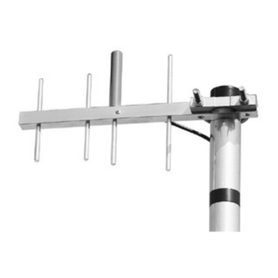
8.3.2 External Antenna Mlink Ultra modules have been approved for use with an external Yagi antenna captured below including a 1.2 dB min cable loss. External antenna types with the same or lower maximum gain are permitted for use with MLink Ultra. Professional installation is required for the external antenna. -
Page 9: Integration Instructions
32 ft min of LMR-400 (3.9 dB/100 ft @ 900 MHz) Integration Instructions MLink Ultra is designed for use in countless wireless applications requiring long range communications with low energy consumption. To ensure that the final product complies with the all of the regulatory requirements for the Modular Grant the following integration instructions should be followed. -
Page 10: Mounting
The recommended footprint is shown in the figure below. Figure 9.1.2 – Recommended MLink Ultra Footprint Minimal circuitry is required to support MLink Ultra and therefore the PCB can be a simple 2 layer FR4 board with ground plane (> 1350 mm ) on the bottom opposite layer to the MLink Ultra module for heat dissipation. -
Page 11: Interfaces
37 - GPIOCLK1 Vmain - Digital Vmain - RF Vpa & Vpwm SW3V0_IN, SW3V0A_OUT, & SW3V0B_OUT Key interface pins shown below. The MLink Ultra datasheet (Ref 4) provides detailed information for all interface pins. Pin # Name Description 16, 18, 24,... - Page 12 GPIOCLK0, measurement, etc AudioOut, GPIOPWM0A, GPIOPWM0B, GPIOCLK1, GPIOD2, GPIO4, GPIO5 (bi-directional) For additional information please contact Aurora Wireless Networks at 403-777-9988 or support@aurorawirelessnetworks.com. 106, 4715 - 13th St. NE, Calgary, Alberta, Canada, T2E 6M3 (403) 777-9988 support@aurorawirelessnetworks.com Confidential and Proprietary...
Need help?
Do you have a question about the MLink Ultra and is the answer not in the manual?
Questions and answers