
Related Manuals for Aurora IPX-TC1-F


Summary of Contents for Aurora IPX-TC1-F
- Page 1 USERS GUIDE IPX Series IPX-TC1-F ● IPX-TC1-C ● IPX-TC2-F ● IPX-TC2-C IPX-TCW3-F ● IPX-TCW3-C 10G 4K IP Distribution IPX-TC1 IPX-TCW3 IPX-TC2 Manual Number: 180101...
-
Page 2: Safety Instructions
Power outlet: To prevent electric shock, be sure the electrical plug used on the product power cord matches the electrical outlet used to supply power to the Aurora product. Use only the power adapter and power connection cables designed for this unit. -
Page 3: Table Of Contents
INTRODUCTION ........................10 About ..............................10 Documentation ............................ 10 Features ............................... 11 IPX-TC1-F, IPX-TC1-C, IPX-TC2-F, IPX-TC2-C Front ............... 12 IPX-TC1-F, IPX-TC1-C, IPX-TC2-F, IPX-TC2-C Rear ................ 14 IPX-TC1-F, IPX-TC1-C, IPX-TC2-F, IPX-TC2-C Bottom ..............15 IPX-TCW3-F & IPX-TCW3-C Front ....................16 IPX-TCW3-F & IPX-TCW3-C Rear ..................... 18 UNDERSTANDING THE BASICS .................... - Page 4 User Guide APPLICATIONS ........................31 Example 1: IPX-TCW3 Configured as Transmitter to IPX-TC1 Configured Receiver ......31 Example 2: IPX Multi-Room ........................ 32 Example 3: Matrix - Multiple IPX to Multiple IPX ................33 Example 4: Video-Wall ........................34 Example 5: KVM utilizing USB 2.0...................... 35 SOFTWARE ..........................
-
Page 5: Package Contents
Please make sure the following items are included within your package. Contact your dealer if any items are missing or damaged. Box Versions IPX-TC1-F-MM • 1 qty IPX-TC1-F Fiber Tranceiver Unit with Mult-mode SFP+ module • 2 qty Mounting Ears and screws IPX-TC1-C •... -
Page 6: Optional Accessories
User Guide OPTIONAL ACCESSORIES • IPX-TC1-RK1 (1RU Rack mount holds 2 units) Includes 4 Rails and 1 Blank • IPX-TC1-RK5 (5RU Rack mount holds 12 units) Includes 24 rails and 4 Blanks • IPX-TC1-BLK (Blank Plate for Rack Mounts) & IPX-TC1-RAIL (For IPX-TC1 use in rack mounts) •... - Page 7 User Guide • IPX-DTE-1 (IPX-TC1 Dante/AES67 Option Card) • IPX-DTE-2 (IPX-TC2 Dante/AES67 Option Card) • QXP-2-IPX (IPX Embedded Linux Server Version)
- Page 8 User Guide • DXB-8/DXB-8i (8 Button Wall Plate) • PS0081-1 (48V 24 Watt PoE Injector) Available in -US, -AU, - EU, and -UK worldwide models. • PS0094-2 (48V 25 Watt Wall Supply) Available in -US, -AU, - EU, and -UK worldwide models. •...
- Page 9 User Guide • RS-232 Adaptor (3.5mm TRS to FEMALE DB9 2-TX 3-RX) CA0052-F2T3R • RS-232 Adaptor (3.5mm TRS to FEMALE DB9 3-TX 2-RX) CA0052-F3T2R • RS-232 Adaptor (3.5mm TRS to MALE DB9 2-TX 3-RX) CA0052-M2T3R • RS-232 Adaptor (3.5mm TRS to MALE DB9 3-TX 2-RX) CA0052-M3T2R •...
- Page 10 User Guide • IPX-SFP-10G20 10G SFP+ Single Mode Dual Module 1310nm 20KM • IPX-SFP-PPC-1 SFP+ 10G Passive Patch Cable 1M (3ft) • IPX-SFP-OM3DXLC-1 OM3 Fiber 50/125 Multi-mode LC Patch Cable 1M...
-
Page 11: Introduction
INTRODUCTION About The IPX Series provides one of the most advanced IP Streaming solutions on the market utilizing Aurora’s IPBaseT™ technology, which synergizes various IP/AV standards to work together as one. It is the industry’s first 4K2K transceiver with zero compression and latency based on BlueRiver NT™/NT+ platform. -
Page 12: Features
User Guide Features Configure as Transmitter (Encoder) or Receiver (Decoder) 4K60 4:4:4 (IPX-TC2), 4K60 4:2:0 (IPX-TC1) Over 10G Fiber or Copper Zero Compression & Zero Frame Latency (22us) for 4K60 4:2:0 and below 3:1 Lossless Compression & Zero Frame Latency (100us) for 4K60 4:4:4 ... -
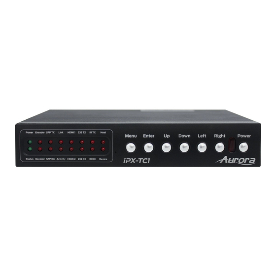
Page 13: Ipx-Tc1-F, Ipx-Tc1-C, Ipx-Tc2-F, Ipx-Tc2-C Front
User Guide IPX-TC1-F, IPX-TC1-C, IPX-TC2-F, IPX-TC2-C Front LEDs • Power/Status – Power will light green when unit is on or in standby. Status will blink at a normal pace during regular operation and slower pace when in standby. • Encoder/Decoder – Encoder (transmit) or Decoder (receiver) will be lit when set accordingly. - Page 14 User Guide Miscellaneous • IR Window – Future use for IR remote. Special Functions • Streaming Factory Default – Press & hold Down and Right together for 10 Seconds. This will only restore default for the mode the unit is currently set to. •...
-
Page 15: Ipx-Tc1-F, Ipx-Tc1-C, Ipx-Tc2-F, Ipx-Tc2-C Rear
User Guide IPX-TC1-F, IPX-TC1-C, IPX-TC2-F, IPX-TC2-C Rear Rear • 48VDC – 48 Volt isolated power input. • SFP+ – Multi-mode or single mode SFP+ 10G modules for the IPBaseT connectivity. • 10G – RJ-45 10G network connection for the IPBaseT connectivity. Unit can be powered with 10G PoE or PoH injector. -
Page 16: Ipx-Tc1-F, Ipx-Tc1-C, Ipx-Tc2-F, Ipx-Tc2-C Bottom
User Guide IPX-TC1-F, IPX-TC1-C, IPX-TC2-F, IPX-TC2-C Bottom Bottom • SO-DIMM Option Card Slot for USB 2.0 and Dante options. Note: The MAC address for the Dante or USB option will be on the card label. -
Page 17: Ipx-Tcw3-F & Ipx-Tcw3-C Front
User Guide IPX-TCW3-F & IPX-TCW3-C Front Buttons • HDMI 1 – Selects HDMI Input 1 (Lights Red, Green, or Blue). • HDMI 2 – Selects HDMI Input 2 (Lights Red, Green, or Blue). • Remote Stream – Selects remote stream assigned when set as decoder (Lights Red, Green, or Blue). - Page 18 User Guide Special Functions • Streaming Factory Default – Press & hold HDMI 1 for 5 seconds. This will only restore default for the mode the unit is currently set to. • Web Server Factory Default – Press & hold HDMI 2 for 5 seconds. •...
-
Page 19: Ipx-Tcw3-F & Ipx-Tcw3-C Rear
User Guide IPX-TCW3-F & IPX-TCW3-C Rear Rear • 48VDC – 48 Volt isolated power input. • SFP+ – For multi-mode or single mode SFP+ 10G modules (IPX-TCW3-F) for the IPBaseT zero compression/latency connectivity. • 10G – RJ-45 10G network connections (IPX-TCW3-C) for the IPBaseT zero compression/latency connectivity. -
Page 20: Understanding The Basics
User Guide UNDERSTANDING THE BASICS Direct Connection with No Ethernet Switch The IPX Series is designed to automatically tunnel the video, audio, USB, RS-232, and IR if they are connected without an Ethernet switch or connected server (QXP-2-IPX). 10GbE Ethernet Switch It is important to use a non-blocking IGMP 10GbE switch with IGMP snooping. -
Page 21: Network Infrastructure
To simplify control of the IPX, QXP-2-IPX is available, an embedded Linux server, which mitigates all communications to all the IPX units (devices and wall plates). The QXP-2-IPX can be controlled via Telnet with Aurora’s IPBaseT Manager, a Microsoft Windows® software. It can also be controlled from other Aurora control products or 3 party control systems with the available API. -
Page 22: Controlling The Ipx With Multiple Servers For Redundancy
User Guide Controlling the IPX with Multiple Servers for Redundancy Multiple QXP-2-IPX servers can run on the same network for redundancy. It is important only one communicates at any given time or incomplete commands may occur between units communicating simultaneously. IPBaseT Manager will only connect to one server at a time but it is important for every PC running IPBaseT Manager they all point to the same server at the same time. -
Page 23: Videowall Capabilities Ipx-Tc1/Ipx-Tcw3
User Guide denominator, which is 2-channel audio, but in cases where you must have surround sound then a down- mixer for the 2-channel destination must be used. In some cases, a custom EDID could be created, as the audio and video are mismatched between the destinations. -
Page 24: Hardware Installation
User Guide HARDWARE INSTALLATION Network Setup 1. Connect a 10GbE network switch and make certain IGMP Snooping features are enabled. 2. Connect fiber or UTP CAT cable accordingly to the network switch and to the IPX units. 3. Connect a QXP-2-IPX Server to the network switch and power on. Follow instructions for the QXP- 2-IPX to set the IP address for remote control. -
Page 25: Qxp-2-Ipx Control Server Setup
User Guide connected, make certain the IPX-USB2 option is installed. 2. Connect power via either 48VDC red euro connector port or the 1GbE PoE port of the IPX unit. If using IPX-TC1-C and want to power the unit through the 10GbE PoE port, make certain it is a 10GbE PoE or PoH injector. - Page 26 User Guide change settings, save EDID, route, and more. If a control system is to be used, make certain it is connected to the same network and follows the Aurora IPX API protocol. Important: • Take note of the MAC Address of every unit. It can be found on the underside or rear of the unit.
-
Page 27: Web Setup Pages
User Guide Web Setup Pages Web Setup pages can be accessed by typing in the IP address of the unit followed by /setup (example: 192.168.100.1/setup). You will then be prompted for a password. Default password is admin. Make certain if all the IPX units are already connected to the 10GbE network that each IPX web server has a unique IP Address or there will be communication issues. -
Page 28: Network Settings
User Guide Network Settings The Network Settings page is to configure the web server IP settings. -
Page 29: Port Settings
User Guide Port Settings Port Settings allow setup of the RS-232 and IR ports. -
Page 30: Ipbt Settings
User Guide iPBT Settings The iPBaseT Settings page is for the video streaming processor. It allows the viewing of the MAC, IP, subnet, and gateway address. In addition, you can select the HDMI inputs and set debug mode in the event diagnostics need to be performed. -
Page 31: Usb Settings
User Guide USB Settings Allows viewing of current USB mode set by the API Server or IPBaseT Manager. Host mode is for a PC to be connected to the USB port of IPX with a Type A to Type A cable (supplied with IPX-USB2 card). Device mode is for USB memory sticks, mouse, keyboard, cameras, etc. -
Page 32: Applications
User Guide APPLICATIONS Example 1: IPX-TCW3 Configured as Transmitter to IPX-TC1 Configured Receiver When the IPX Series is connected point to point, no configuration is required, as the units will auto identify and make a tunnel between both ends for the video, audio, RS-232, IR, USB, and Ethernet. With the copper version a maximum distance of 100m (328ft) can be achieved. -
Page 33: Example 2: Ipx Multi-Room
User Guide Example 2: IPX Multi-Room The IPX Series is perfect for multi-room applications with its flexibility. A nearly unlimited number of rooms can share video, audio, data, and control in real-time. The scalability is only limited by the size of the network switch and infrastructure. -
Page 34: Example 3: Matrix - Multiple Ipx To Multiple Ipx
User Guide Example 3: Matrix - Multiple IPX to Multiple IPX The IPX can take the place of any typical card cage matrix system, adding flexibility and performance never seen before. Even features like seamless switching is no longer a premium. -
Page 35: Example 4: Video-Wall
User Guide Example 4: Video-Wall The IPX Series is capable of 4K video-walls. Up to 2x2 size can be created with 4K input and all with no compression and zero latency for the IPX-TC1 and 16x16 for the IPX-TC2. It is important to read Understanding the Basics section of this manual when specifying videowall usage. -
Page 36: Example 5: Kvm Utilizing Usb 2.0
User Guide Example 5: KVM utilizing USB 2.0 Command & Control and NOC centers are perfect for the IPX Series, especially with the advanced break- away switching and USB 2.0 running at a full 480Mbps. With the IPX it is no longer just keyboard and mouse but full USB peripheral routing as well. -
Page 37: Software
User Guide SOFTWARE IPBaseT Manager PC Control Tool The IPBaseT Manager is a Windows® based software available at the Aurora customer portal on www.auroramm.com IPBaseT Manager allows a user to control the various capabilities of IPX series products on a network. - Page 38 • Touch Screen Friendly Layout • Configuration File for Cloning Presets and Connections on Other PCs • Multi-Server connections For full detail of the IPBaseT Manager software tool and setup, the manual can be found at the Aurora website www.auroramm.com...
-
Page 39: Connector Pin Definition
User Guide CONNECTOR PIN DEFINITION HDMI Pin 1 TMDS Data2+ Pin 8 TMDS Data0 Shield Pin 15 Pin 2 TMDS Data2 Shield Pin 9 TMDS Data0– Pin 16 Pin 3 TMDS Data2– Pin 10 TMDS Clock+ Pin 17 DDC/CEC Ground Pin 4 TMDS Data1+ Pin 11 TMDS Clock Shield... -
Page 40: Rs-232
User Guide RS-232 The RS-232 is a 3.5mm TRS connector. Tip is TX (output), ring is RX (input), and Sleeve is ground. To simplify connections Aurora offers pre-molded RS-232 cables in null and none nulled in male and female DB9. -
Page 41: Ir (Infrared)
User Guide IR (Infrared) It will autosense a TS or a TRS connector to determine if an IR emitter (TS) or IR receiver (TRS) is inserted. The IR receiver must be with carrier inverted to work. The tip is signal, ring is 5V, and sleeve is ground. -
Page 42: Appendix 1 Troubleshooting
User Guide APPENDIX 1 Troubleshooting It is advisable to make certain all units are using the latest firmware before troubleshooting. Why IPBaseT Manager cannot find any devices? • Check the IP Address of the QXP-2-IPX server and make certain it is connected on the same network. - Page 43 User Guide Audio not working • Make certain correct audio path is selected. The IPX can choose between analog input and HDMI. • Verify correct EDID usage. If EDID has 5.1 surround sound listed and display cannot do 5.1 there will be no audio.
- Page 44 User Guide Videowall mode not working correctly • As per the Understanding the Basics videowall section, some displays will not work well with the IPX-TC1 based on bezel compensation or input resolution relative to the videowall size. Please refer to that section. IPX-TC2 model does not have these limitations and is the recommended model for Videowall usage.
-
Page 45: Appendix 2
You must be signed up to the Customer Portal in order to download firmware with instructions on how to update. APPENDIX 3 Protocol For the latest protocol please go www.auroramm.com You must be signed up to the Customer Portal in order to download IPX protocol. The protocol is only available to authorized Aurora dealers. -
Page 46: Appendix 4 Recommended Cabling
For the copper, unshielded cable is preferred for optimal performance. While any properly made cable will work with the IPX series the models below have been tested by Aurora with the IPX at full bandwidth and distance. Fiber with copper for remote power... -
Page 47: Appendix 5 Recommended Network Switches
Below are some models that have been tested with the IPX Series. For a more complete listing, the IPX Series Network Switch Recommendations and Configuration guide can be found on the Aurora website. www.auroramm.com 5.1 Switch Speed The IPX Series requires the switch to be a 10 GbE. -
Page 48: 5.3 Ethernet Switch Configuration
The end results are a noticeably shorter video switching time. Aurora recommends to always enable the FASTLEAVE option when available. With FASTLEAVE option, seamless switching is possible for 4K video sources. Without FASTLEAVE option, 'seamless' switching is limited to 1080P 60 Hz video signals. -
Page 49: 5.4 Ethernet Switch Models
User Guide 5.4 Ethernet Switch Models The IPX Series Network Switch Recommendations and Configuration guide can be found on the Aurora website. www.auroramm.com... -
Page 50: Appendix 6
User Guide APPENDIX 6 Technical Specifications Model Name IPX-TC1 & IPX-TCW3 Technical Compression Zero Latency Zero HDMI Inputs HDMI Outputs Audio Analog Stereo Line In/Out (3.5mm TRS Tip is Left, Ring is Right, Sleeve is Ground) 10G Fiber Ethernet SFP+ (Single Mode or Multi-Mode) 10G Copper Ethernet RJ-45 330ft with CAT 6A RJ-45 10/100/1000M PoE (PSE) -
Page 51: Appendix 7 Warranty
Limited 3 Year Warranty Aurora Multimedia Corp. (“Manufacturer”) warrants that this product is free of defects in both materials and workmanship for a period of 3 years as defined herein for parts and labor from date of purchase. This Limited Warranty covers products purchased in the year of 2009 and after. - Page 52 User Guide Aurora Multimedia Corp. 205 Commercial Court Morganville, NJ 07751 Phone: 732-591-5800 Fax: 732-591-6801...
Need help?
Do you have a question about the IPX-TC1-F and is the answer not in the manual?
Questions and answers