
Related Manuals for Extech Instruments PQ3450-30


Summary of Contents for Extech Instruments PQ3450-30
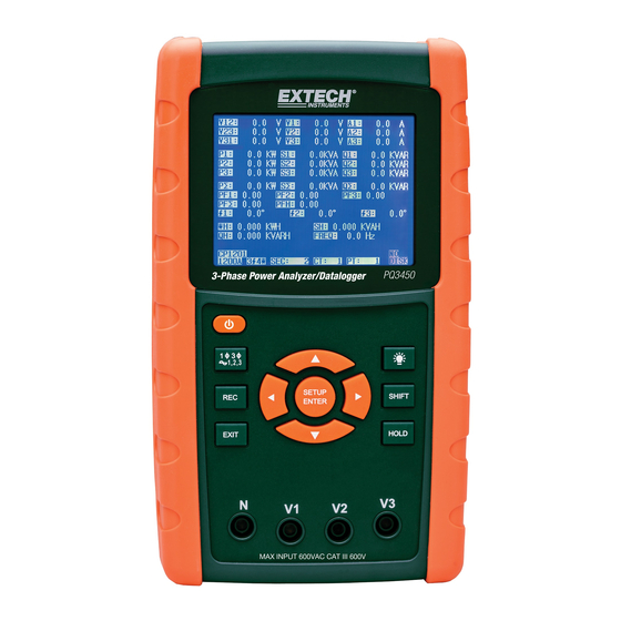
- Page 1 USER MANUAL 3-Phase Power Analyzer/Datalogger MODEL PQ3450 Additional User Manual Translations available at www.extech.com...
-
Page 2: Table Of Contents
Table of Contents 1.0 INTRODUCTION 1-1 Features....................3 1-2 Safety ....................... 4 2.0 SPECIFICATIONS 2-1 General Specifications ................5 2-2 Electrical Specifications................6 3.0 METER DESCRIPTION .................. .7 4.0 METER BASICS AND THE SETUP MODE 4-1 Initialization Screen ................... 8 4-2 Measurement Screen Example .............. -
Page 3: Introduction
1.0 Introduction Congratulations on your purchase of the Model PQ3450 Power Analyzer/datalogger. This instrument is fully tested and calibrated prior to delivery; proper use and care of this meter will provide years of reliable service. 1.1 Features Large dot-matrix, numerical, backlit LCD ... -
Page 4: Safety
1.2 Safety CAUTION: Risk of electric shock. Do not attempt to open or disassemble the meter while taking measurements CAUTION: Do not attempt to measure Voltage or Current that exceeds specified limits Do not operate this instrument in wet or dusty environments. ... -
Page 5: Specifications
2.0 Specifications 2.1 General Specifications Circuit Custom single-chip microprocessor LSI circuit LCD Size: 81.4 X 61 mm (3.2 X 2.4”) Display Dot Matrix backlit LCD (320 X 240 pixels) Measurements V (voltage phase to phase) V (voltage phase to ground) A (Current Phase to ground) KW / KVA/ KVAR / PF (Phase) KW / KVA/ KVAR / PF (System) -
Page 6: Electrical Specifications
Real time data logger saves data to SD memory card for download to PC Datalogger (data files open directly to spreadsheet) Sampling rate: From 2 seconds to 7200 seconds (2 hours) Max. File capacity: 30,000 records Data Output RS232 port Operating Temperature 0 to 50 C (32 to 122 Operating Relative... -
Page 7: Meter Description
3.0 Meter Description Meter Front 3-1 LCD Display 3-2 ◄ Left arrow navigation 3-3 Power ON-OFF 3-4 Phase / Wire setup 3-5 REC datalogger memory 3-6 Exit button 3-7 Setup/Enter button 3-8 Measurement input terminals 3-9 ▼Down arrow navigation 3-10 HOLD (freeze display) 3-11 Shift button 3-12 Display Backlight ON-OFF 3-13 ►... -
Page 8: Meter Basics And The Setup Mode
4.0 Meter Basics and Setup Mode 4-1 Initialization Screen 1. When the meter is switched ON the initialization screen appears. Start-up Initialization Screen 2. The meter will also check for an inserted SD memory card. ‘SD check’ will appear on the lower right side of the display. -
Page 9: Keypad Summary
4.3 Keypad Summary POWER : Press and hold to power ON/OFF 1Φ 3Φ (phase/wire) : Select (1P/2W, 1P/3W, 3P/3W, 3P/4W) measurement function REC : Data record key for use with the SD Memory Card HOLD : Freeze the displayed reading ... - Page 10 Setup Mode Screen 4.4.2 The Setup Mode Parameter Menu Folder Name: Select a file name on the SD CARD; the range is WTA01 to WTA10 File Name: Set a file name on the SD CARD (50 filenames are permitted) ...
-
Page 11: Setup Mode In Detail
4.5 Setup Mode in Detail Press SETUP to enter the Setup Mode, selected items will appear highlighted (reverse video). Use the up and down arrow keys to move through the available parameters and use the Shift key to open a parameter for editing. Once a parameter is opened for editing, the up and down arrow keys are used again to change a parameter’s setting. - Page 12 4.5.2 File name: Set a file name in the SD Memory Card In the Setup Mode, scroll down to the FILE NAME parameter using the up and down arrow keys The screen will show the "NO FILE" indicator in the REC Date option area when the selected file is new.
- Page 13 Press SHIFT again and the “SHIFT 2” icon will appear on the upper right side of the screen and the second half of the File Name, which the user can customize as needed, will be highlighted. Use the arrow keys to select a number between 001 and 0050 inclusive. . File Name Examples: 1P201001: 1P2 is one phase by two wires, 01 is the folder number, and 001 is the file number 1P301001: 1P3 is one phase by three wires, 01 the folder number, and 001 the file number...
- Page 14 4.5.6 Potential Transformer (PT) Setup In the Setup Mode, use the up and down arrow keys to scroll to the PT field. Press SHIFT, the display "SHIFT1" will switch ON Use the ▲ or ▼ keys to adjust the PT value (the range is 1 to 1000) Press SHIFT again to return to Setup Mode editing or press EXIT to leave the Setup mode.
- Page 15 4.5.10 Set Clamp type In the Setup Mode, use the up and down arrow keys to scroll to the CLAMP TYPE field. Press SHIFT, the display "SHIFT1" will switch ON Use the ▲ or ▼ keys to select the full scale setting of the clamp used. Press SHIFT again to return to Setup Mode editing or press EXIT to leave the Setup mode.
- Page 16 4.5.14 Set Time and Date In the Setup Mode, use the up and down arrow keys to scroll to the YEAR, MONTH, DATE, HOUR, MINUTE, and SECOND fields. Press SHIFT key when the desired field is selected, the display "SHIFT1" will switch ON Use the ▲...
-
Page 17: Power Measurement Procedures
5.0 Power Measurement Procedures 1Φ2W (Single Phase - Two Wire) Measurement Power the instrument ON by pressing the ‘Power’ key, and then use the ‘1Φ 3Φ’ key to select the 1Φ 2W system, the selected name of the system will be shown on the bottom left side of the display Connect the line voltage L1, Vn (Neutral) to V1 and N terminals of the instrument. -
Page 18: 3W (Single Phase Three Wire) Measurement
1Φ3W (single phase - three wire) Measurement Power the instrument ON by pressing ‘Power’ key, and then press the ‘1Φ 3Φ’ key to select 1Φ 3W, the selected name of the configuration will appear on bottom left hand side of the display. Connect the line voltage L1, L2 and Vn (Neutral) to V1, V2 and N terminals of the instrument Connect the two (2) clamps (A1 and A2) to the conductors (A1) and (A2) -
Page 19: 3W (Three Phase Three Wire) Measurement
3Φ3W (three phase - three wire) Measurement Power the instrument ON by pressing the ‘Power’ key, and then press ‘1Φ 3Φ’ to select 3Φ 3W, the selected configuration name will appear on bottom left hand side of the display. Connect the line voltage L1, L2 and L3 to V1, V2 and V3 terminals of the instrument. Connect the three (3) clamps (A1, A2, A3) to conductors A1, A2 , A3 Connect the three (3) Clamps to the meter using the A1, A2, and A3 terminals The related measurement factors will appear on the display... -
Page 20: 4W (Three Phase Four Wire) Measurement
3Φ4W (three phase - four wire) Measurement Power instrument ON by pressing the ‘Power’ key, and then press ‘1Φ 3Φ’ to select the 3Φ 4W system, the selected name of the system will appear on the bottom left hand side of the display. -
Page 21: Ct And Pt Measurement
5.5 Current (CT) / Potential (PT) Transformer Measurement Power the instrument ON by pressing the ‘Power’ key , and then press the ‘1Φ 3Φ’ key to select the 3Φ 4W system, the selected name of the system will appear on the bottom left hand side of the display. -
Page 22: Data Logger
5.6 Datalogger Function Press the REC key once to begin. If the meter displays the "Change Card" message at the bottom right, the SD CARD memory is either full or it is damaged. If the meter displays “NO DISK” an SD card must be inserted. If ‘Check SD’... -
Page 23: Data Hold
5.7 Data Hold Function During a measurement, press the HOLD KEY once, the displayed readings will freeze and the display will show the “HOLD” icon on the bottom right side of the screen Press the HOLD key again to release the display and return to the normal operating mode. -
Page 24: Measurement Definitions
5.10 Measurement Definitions V12, V23, V31 : Line Voltage V1, V2, V3 : Phase Voltage A1, A2, A3 : Line Current P1, P2, P3 : True Power of each phase (W) S1, S2, S3 : Apparent Power of each phase. (VA) ... -
Page 25: Maintenance
6.0 Maintenance CAUTION: Remove test leads before opening the battery cover; Electrical Shock Hazard. 6.1 Cleaning CAUTION: When cleaning, use only a dry cloth. Do not use liquids of any kind to clean the meter. 6.2 Battery Replacement When the display shows the LOWBAT indicator, replace the batteries as soon as possible Open the rear Battery Cover and remove the batteries Replace the eight (8) batteries (1.5Vdc ‘AA’... -
Page 26: Pc Interface 7-1 Download Data From Sd Card
7.0 SD Card 7.1 Download SD Card Data to PC After a Datalogging session, remove the SD card from the SD card socket. Plug the SD card into a PC SD card reader slot or into an SD card reader adaptor. Power the computer and run spreadsheet software.
Need help?
Do you have a question about the PQ3450-30 and is the answer not in the manual?
Questions and answers