Table of Contents
Advertisement
Quick Links
User's Guide
PM200
Fiber Optic Power Meter
Introduction
Congratulations on your purchase of the Extech PM200 Fiber Optic Power Meter. The
PM200 is a high accuracy high resolution optical power meter. It is NIST traceable at
850, 1300, 1310 and 1550nm making it ideal for both single-mode and multimode fiber
testing. The PM200 can store up to 100 measured datapoints. This stored data can be
downloaded via the software to produce formatted certification reports. Careful use of
this meter will provide years of reliable service.
Advertisement
Table of Contents

Related Manuals for Extech Instruments PM200


Summary of Contents for Extech Instruments PM200
- Page 1 Congratulations on your purchase of the Extech PM200 Fiber Optic Power Meter. The PM200 is a high accuracy high resolution optical power meter. It is NIST traceable at 850, 1300, 1310 and 1550nm making it ideal for both single-mode and multimode fiber testing.
-
Page 2: Table Of Contents
1.8.4 Connectors and Splices Input 1.8.5 Company Selection 1.8.6 Name Input 1.8.7 Summary View 1.8.8 Report Printing 1.8.9 Example Printout 1.9 Clearing Data 2.0 PC Based Meter Control 3.0 Battery Replacement 4.0 PM200 Data Storage Error Codes Warranty PM200 V1.0 11/04... -
Page 3: Specifications
Resolution (dB) 0.01 General Specifications Battery Life 100+ hours (9-volt) Optical Connector 2.5mm universal Data Storage up to 100 storage points Download DB-9 serial Software Reporter Dimensions 4.94 x 2.75 x 1.28 in Weight (with battery) 10 ounces PM200 V1.0 11/04... -
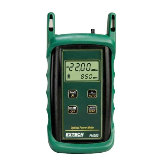
Page 4: Description
Detector Port Tone Mode Power Reading Battery Indicator -20.28 Data Indicator. 1310 Units Indicator Wavelength Indicator 10. SAVE / DOWNLOAD button 11. ON / OFF / Backlight button 12. λ / AUTO button 13. UNITS / ZERO button PM200 V1.0 11/04... - Page 5 ST, SC, or FC connectors equally well without any loss of accuracy. There is no need to change or maintain expensive adapter caps. Tone Mode - When ‘Hz’ is visible on the display, the PM200 is checking for the presence of a modulated optical signal. These modulated signals are used to automatically switch wavelengths when they are sent by an OWL light source with modulation capability.
-
Page 6: Operation
1.2.2 Patch Cords - Patch cords may be needed to connect the PM200 to the system under test. The connector styles on the patch cord must match the type on the PM200 and the type of the system under test. -
Page 7: Typical Applications
1.3 Typical Applications PM200 test kits can be used as diagnostic and measurement tools of optical transmission systems and fiber optic links. These applications can be found in several industries, including premise, LAN, CATV, and Telco. Two types of measurements are possible with the PM200 optical power meter: optical power and optical loss. -
Page 8: Optical Power Measurement
Power on the EUT, set it to the desired wavelength, and allow it to stabilize. Power on the PM200, and set it to match the wavelength of the EUT. Set the units to dBm. The resultant reading is the output power. (The example in Figure 2 shows an -20.58... -
Page 9: Optical Loss Measurement (Set Reference)
(see Figure 2 on the previous page). If it is good, then remove it from the PM200 and light source and set it aside. This will be the patch cord for the meter side. -
Page 10: Optical Loss Measurement
LINK UNDER TEST Connect the PM200 and light source to opposite ends of the link under test. The PM200 will show the amount of loss in the link (in dB). Figure 4 shows a power level of -2.45 PATCH PANELS PATCH PANELS dB. -
Page 11: Data Storage
Connect the PM200 and light source to opposite ends of the link under test. Press the SAVE / DOWNLOAD button. The PM200 will store a data point for each wavelength, and will briefly show the number of data points currently stored in place of the wavelength. -
Page 12: Downloading Data Into Pc With Reporter Software
1.8 Downloading Data to a PC With Reporter Software Once testing is complete or the PM200’s memory is full, the stored data points may be downloaded to a PC running the Reporter software. A Pentium PC (or better) running Windows 95 or later operating system is required for Reporter Software. Please use the included CD to install the software. -
Page 13: Standard Selection
1.8.1.2 - Select the cabling standard from the drop-down list. 1.8.1.3 - Once the cabling standard has been chosen, the wavelengths and fiber types that the standard supports appear in the boxes on the right. Click Next to continue. PM200 V1.0 11/04... -
Page 14: Fiber Type Selection
The selected fiber type should match the type of fiber of the link under test. 1.8.2.3 - Once the fiber type has been chosen, it appears in the dropdown box. Click Next to continue. PM200 V1.0 11/04... -
Page 15: Fiber Length Input
This length will apply to all of the data points downloaded from the PM200. Type the length in the input box, and select the length units at the right. 1.8.3.2 - Once the fiber link length and the length units are entered. -
Page 16: Connectors And Splices Input
1.8.4 - Connectors and Splices Input 1.8.4.1 - If there are any connections or splices in the link, enter them into the input boxes. 1.8.4.2 - Once the number of connections and splices have been entered. Click Next to continue. PM200 V1.0 11/04... -
Page 17: Company Selection
1.8.5.3 - Once the organization’s name and telephone number have been entered, click OK to continue. 1.8.5.4 - The organization name should now appear in the dropdown box. Click Next to continue. PM200 V1.0 11/04... -
Page 18: Name Input
1.8.6 - Name Input 1.8.6.1 - Enter a descriptive name for the link into the input box. 1.8.6.2 - Once the link name has been entered, click Finish to continue. PM200 V1.0 11/04... -
Page 19: Summary View
To print the current view to a PC printer, press the print button highlighted at right to print the Summary report. The printed report will look very much like the screen. See an example report on the next page. PM200 V1.0 11/04... -
Page 20: Example Printout
Circuit ID - this is the name of the fiber that was tested P/F - shows whether the test passed or failed 850nm - shows the amount by which the test passed or failed by at the wavelength tested PM200 V1.0 11/04... -
Page 21: Clearing Data
PM200. To clear data from the PM200, while the unit is OFF, press and hold the SAVE / DOWNLOAD button and press the ON / OFF / Backlight button. The icon will disappear from the display when the data has been successfully erased. -
Page 22: Pc Based Meter Control
Key: C Function: Clear memory Description: Pressing the ‘C’ key is the equivalent to holding the SAVE / DOWNLOAD button on the PM200 while the unit is powered ON. The data indicator icon will disappear from the display. Key: D Function: Download memory Description: Pressing the ‘D’... -
Page 23: Battery Replacement
The battery compartment is covered by a sliding plate on the back of the unit. Remove the rubber boot to expose the back of the unit. One 9v battery is required for operation. 4.0 PM200 Data Storage Error Codes ERR - the user has not waited long enough to get data stored for both wavelengths... -
Page 24: Warranty
Warranty EXTECH INSTRUMENTS CORPORATION warrants this instrument to be free of defects in parts and workmanship for one year from date of shipment (a six month limited warranty applies to sensors and cables). If it should become necessary to return the instrument for service during or beyond the warranty period, contact the Customer Service Department at (781) 890-7440 ext.
Need help?
Do you have a question about the PM200 and is the answer not in the manual?
Questions and answers