Table of Contents
Advertisement
Available languages
Available languages
Quick Links
Advertisement
Table of Contents

Related Manuals for Eurosystems Z2RG


Summary of Contents for Eurosystems Z2RG
- Page 1 Bedienungsanleitung für Z2RG Motorhacke Stand 01.06.2018 eurosystems Deutschland Motorgeräte Handelsgesellschaft mbH Im Fuchshau 14 D-73635 Rudersberg Tel: +49 7183 / 30 590-0 Fax: +49 7183 / 30 590-20 info@eurosystems.info www.eurosystems.info...
- Page 5 Leggere il manuale prima di usare la macchina - Attenzione: rotazione fresa. Read the instructions manual before operating on the machine - Danger tiller rotation. Lire le mode d’emploi avant l’usage - Attention: danger rotation fraise. Lesen Sie die Gebrauchsanweisung vor der Inbetriebnahme - Achtung: frasenrotation.
- Page 6 • Marcia avanti • Retromarcia • Forward drive • Reverse drive • Marche avant • Marche arrière • Etichetta indicazione filo retromarcia • Fahrantrieb vorwärts • Rückwärtsgang • Label for reverse wire • Marcha adelante • Marcha atrás • Plaquette pour fil à marche arrière •...
-
Page 7: Norme Di Sicurezza
Istruzioni originali INTRODUZIONE Indice Gentile cliente, la ringraziamo per la fiducia accordata ai nostri prodotti e le auguriamo un piacevole utilizzo della sua macchina. Introduzione Abbiamo creato queste istruzioni per l’uso allo scopo di assicurare, fin dall’inizio, un funzionamento privo di inconvenienti. - Page 8 frese girano intervenire sul registro di regolazione del tendicinghia). 5 Durante il lavoro, per maggiore protezione, vanno indossate protezioni acustiche (cuffie e/o tappi), calzature antinfortunistiche e pantaloni lunghi. Fare attenzione, la fresa in movimento è potenzialmente pericolosa per mani e piedi. Importante inoltre camminare e non correre durante il lavoro.
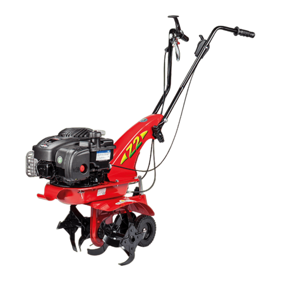
- Page 9 MONTAGGIO STEGOLA (Fig. 4a) Fissare i due tubi stegola (6) al supporto (1) con la vite (7), il distanziale (13), due rondelle (8) e il dado (9) nei fori (A). Eseguire lo stesso procedimento per i fori (B) inserendo la vite (7), pomolo (10), distanziale (13), due rondelle spessore 4 mm.(12) e l’altro pomolo (10) nell’ordine come rappresentato in figura.
- Page 10 energico. - Marcia avanti (Fig. 6) : A motore avviato appoggiare i coltelli sul terreno e, tenendo saldamente la motozappa, infilare nel terreno lo sperone. Impugnare le stegole e premere il fermo di sicurezza (13) che impedisce l’innesto accidentale delle frese. Tirare la leva avanzamento (2) per tutta la sua corsa. - Marcia indietro: rilasciare la leva avanzamento (fig.6, part.2) e tirare verso di sé...
- Page 11 RUMORE AEREO E VIBRAZIONI Valore rilevato di potenza acustica LWA = 92 dB (A), con coefficiente di incertezza K = ±1 dB (A). Valore di pressione acustica, secondo normativa En709, Leq = 77,3 dB (A) con coefficiente di incertezza K = ±1,1 dB (A) per modello Z2. Leq = 83 dB (A) per modello Z3, con coefficiente di incertezza K = ±1,2 dB (A).
-
Page 12: Safety Precautions
Translation of original user instructions INTRODUCTION List of contents Dear Customer: Thank you for your trust in purchasing our products. We wish you to enjoy using our machines. The following working instructions have been issued to ensure reliable operation from the beginning. If you Introduction carefully follow such information the machine will operate with complete satisfaction have a long service life. - Page 13 5 During operations you need to use ear protectors, sturdy footwear and long trousers should be worn. Be very careful, when working, the blade is potentially hazardous for hands and feet. Always walk and never run while operating the machine. 6 During the machine transport and all the maintenance, cleaning, equipment change operations, the engine must be switched off.
- Page 14 HOW TO ASSEMBLY AND ADJUST THE HANLEBARS (Fig.4a) Fix the 2 handlebar tubes (6) to the support (1) with the screw (7), the spacer (13), 2 washers (8) 1 nut (9) into the holes (A). Perform the same proceeding with the holes (B) inserting the screw (7), the handle (10), the spacer (13), 2 washers thickness 4 mm.(12) and the other handle (10) in the order as shown in the picture.
- Page 15 lever (2) all its way long. - Reverse speed: release the forward lever (fig. 6, part 2) and pull the other lever on the handlebar towards you.(1) This motor hoe has been designed to produce minimum vibrations and noise. Nevertheless, it is a good idea to interrupt long jobs with short pauses.
-
Page 16: Troubleshooting
Measured sound pressure level with En709, Leq = 77,3 dB (A), with a uncertainty value K = ±1,1 dB (A) for mod. Z2 and Leq = 83 dB (A), with a uncertainty value K = ±1,2 dB (A) for mod. Z3. Handlebar vibration in compliance with EN 709 and ISO 5349. Level max detected = 7,2 m/s , uncertainty value K = ±3,6 m/s for mod. -
Page 17: Mesures De Securite
Traduction du mode d’emploi original INTRODUCTION Table des matières Cher client, nous vous remercions de la confiance que vous nous témoignez et vous souhaitons beaucoup de satisfaction dans son utilisation. Afin de garantir d’emblée un fonctionnement sans accrocs nous avons créé cette notice Introduction d’utilisation. - Page 18 se mettre en marche (si c’était le cas, agir sur la vis de réglage du tendeur de courroie). 5 Porter des gants, des chaussures de sécurité avec semelles antidérapantes, des lunettes de protection. Utilisez des coquilles anti-bruit pour la protection de l’appareil auditif. Attention : la fraise en mouvement représente un danger potentiel pour les mains et les pieds. Il est aussi très important de marcher et pas de courir pendant le travail.
- Page 19 MONTAGE DU SUPPORT DE MANCHERON (Fig. 4) Monter le support (1) sur la motobineuse en le fixant par les 4 vis (2) déjà montées sur la plaque, les rondelles (3) et les écrous (4). Monter le passe-fil (5) comme l’indique la figure. MONTAGE DU MANCHERON (Fig.
-
Page 20: Nettoyage Et Entretien
- Mise en marche du moteur : ouvrir le robinet du carburant (pour les moteurs qui en sont équipés) et mettre le levier de l’accélérateur (Fig. 8 rep. 1) sur START. Pour le démarrage à froid, veuillez consulter la notice du moteur. Saisir la poignée du lanceur et tirer d’un coup énergique. - Marche avant (Fig. - Page 21 CARACTERISTIQUES TECHNIQUES DE LA MOTOBINEUSE MOD. Z3 Moteur : pour tout renseignement, veuillez consulter la notice respective. La largeur de travail des fraises est de 50 cm, y compris le capot de protection. La vitesse maximum de rotation de la fraise est d’environ 130 tours/minute.
- Page 22 Übersetzung der originalen Betriebsanleitung EINLEITUNG Inhaltsverzeichnis Verehrter Kunde, wir bedanken uns für Ihr Vertrauen, das Sie in unsere Qualitätsprodukte setzen und wünschen Ihnen viel Freude beim Arbeiten mit Ihrem neuen Gerät. Um eine zuverlässige Inbetriebnahme von vornherein zu Einleitung gewährleisten haben wir diese Betriebsanleitung geschaffen. Wenn Sie die folgenden Hinweise genau beachten, wird Ihr Gerät stets zu Ihrer vollsten Zufriedenheit arbeiten und eine lange Lebensdauer besitzen.
- Page 23 und Füße gefährlich sein. Wichtig: Bei der Arbeit gehen und nicht schnell laufen. 6 Während des Transports der Maschine und aller Wartungsarbeiten, dem Reinigen und dem Wechsel der Geräte muss der Motor immer abgeschaltet sein. 7 Entfernen Sie sich erst dann von der Maschine, wenn man den Motor abgeschaltet hat. 8 Die Maschine nicht in geschlossenen Räumen laufen lassen, wo die entstehenden Abgase sich anhäufen könnten.
- Page 24 Abstandsstück (13), zwei Unterlegscheibe Dicke von 4mm (12) und den anderen Drehknopf (10) in der auf der Abbildung gezeigten Reihenfolge einführt. Die Führungsholme sind höhenverstellbar. Die Drehknöpfe (10) abschrauben und die Durchsteckschraube (7) in das Loch stecken, das am besten für Ihre Arbeit geeignet ist. Die Standard-Einstellung ist auf Höhe der Hüfte. MONTAGE DES GASHEBEL-KABELS (Abb.
- Page 25 Motorhacke gut festzuhalten ist. Den Handholm ergreifen, die Sicherungssperre (13) drücken, sodass die zufällige Einschaltung des Hacksatzes verhindert wird und den Vorschubhebel ganz ziehen (2). - Rückwärtsgang: Den Vorschubhebel loslassen (Abb. 6, Teil 2) und den anderen am Holm angebrachten Hebel (1) zu sich hin ziehen. Diese Motorhacke ist konzipiert, um Vibrationen und Lärmemissionen auf ein Minimum zu verringern.
- Page 26 Vorwärtsgang + 1 Rückwärtsgang. Gewicht der ganzen Motorhacke: 44 kg. Abmessungen der Motorhacke: Max. Länge 1,30 m, max. Breite 0,50 m, Höhe 1,10 m. LÄRMEMISSION UND VIBRATIONEN Höchstzulässige Schallwerte ist LWA = 92 dB(A), Messunsicherheit K = ±1 dB (A). Schallleistungspegel laut Richtlinie En 709, Leq = 77,3 dB(A), Messunsicherheit K = ±1,1 dB (A) bei der mod.
-
Page 27: Instrucciones De Seguridad
Traducción del manual de instrucciones original INTRODUCCIÓN Contenido Estimado cliente: Lo felicitamos por su compra y le agradecemos su confianza. Esperamos que esta máquina sea de su agrado durante muchos años. Con el fin de garantizar un funcionamiento correcto, hemos creado este folleto de Introducción utilización. - Page 28 5 Utilice guantes, zapatos de protección contra los cortes con suela anti-resbalones, gafas protectoras. Utilice auricolares para proteger el oído. Tenga cuidado ya que la fresa en movimiento es potencialmente peligrosa para las manos y los pies. Además, es importante caminar y no correr durante el trabajo.
- Page 29 MONTAJE MANCERA (Fig. 4a) Montar los dos tubos del manillar (6) al soporte (1) con el tornillo (7), el espaciador (13) dos arandelas (8) y la tuerca (9) en los agujeros (A). Hacer lo mismo en los agujeros (B) poniendo el tornillo (7), el puño (10), espaciadores (13), dos arandelas de 4mm (12) y otro puño (10) así...
- Page 30 las fresas y tirar la palanca de avance (2) hasta el final de su carrera. - Marcha hacia atrás: soltar la palanca de avance (Fig. 6, part.2) y tirar hacia si mismo la otra palanca situada en la mancera.(1) - Esta motoazada ha sido proyectada para reducir al mínimo las emisiones de vibraciones y ruido, sin embargo, es aconsejable intercalar los trabajos de larga duración con pequeñas pausas.
- Page 31 RUIDO AEREO Y VIBRACIONES Valor de potencia acústica según EN 709, Lwa = 92 dB(A). Coeficiente de incertidumbre K = ±1 dB(A). Valor de presión acústica en el lugar de trabajo según EN 709 Leq = 77,3 dB(A). Coeficiente de incertidumbre K = ± 1,1 dB (A) para la motoazada mod.
-
Page 32: Normas De Segurança
Tradução do manual original INTRODUÇÃO Indice Excelentíssimo cliente, agradecemos a confiança que demonstrou nos nossos produtos e fazemos votos para que a utilização da sua máquina seja sempre agradável. Redigimos estas instruções de uso com a finalidade de garantir um funcionamento da máquina sem problemas desde o começo. - Page 33 movimento são potencialmente perigosos para as mãos e os pés. Também é importante, durante o trabalho, caminhar e não correr. 6 Durante o transporte da máquina e todas as operações de manutenção, limpeza, troca das alfaias, o motor deve estar desligado. 7 Desligar o motor da máquina antes de a abandonar.
- Page 34 MONTAGEM DO CABO DO ACELERADOR (Fig. 5) O cabo acelarador já vem montado no motor e no acelerador mesmo (3). O acelerador tem que ser montado no furo (A) do guiador por o parafuso (2) e bloqueado por a porca (1) tendo cuidado que a alavanca (4) esteja livre. MONTAGEM DO CABO COMANDO TENSOR DA CORREIA (Fig.
-
Page 35: Manutenção Do Motor
duração com pequenas pausas. Fim trabalho: uma vez acabado o trabalho, para parar o motor, colocar a alavanca do acelerador (fig. 5 part. 2) na posição STOP. SUBSTITUIÇÃO DO ÓLEO NA TRANSMISSÃO INFERIOR (Fig. 9) Em geral deve-se substituir o óleo cada 100 horas de trabalho (viscosidade do óleo SAE 80). - Page 36 Vibrações max. nas braços de acordo com EN 709 e ISO 5349. Valor medido = 7,2 m/s , coeficiente de incerteza K = ±3,6 m/s para mod. Z2 e Valor medido = 8,6 m/s , coeficiente de incerteza K = ±4,3 m/s para mod.
-
Page 37: Varnostni Ukrepi
Prevod izvirnih navodil za uporabo PREDSTAVITEV Kazalo vsebine Dragi uporabnik, zahvaljujemo se vam za vaše zaupanje, ki ste nam ga izkazali z nakupom našega izdelka. Upamo, da boste pri njegovi uporabi uživali. Ta navodila za uporabo so izdana za zagotavljanje pravilne in ustrezne uporabe izdelka: Predstavitev iz tega razloga vas prosimo, da pazljivo sledite delovnim in varnostnim navodilom, za nemoteno delovanje in dolgo življenjsko dobo vaše naprave. - Page 38 če stojite pred napravo ali sestavnimi deli oz. priključki. Ko potegnete za zaganjalno vrvico, se kultivator ali vrtljivo rezilo ne smeta premikati (če se to zgodi, je potrebna prilagoditev na kontrolni matici napenjalca jermena). 5 – Kultivatorjeva rezila lahko poškodujejo vaše noge, zato je med delovanjem potrebno uporabljati ščitnike za ušesa, ustrezno obutev in dolge hlače.
- Page 39 MONTAŽA IN NASTAVITEV KRMILNIH ROČAJEV( SL-4a) 2 cevi krmilnega mehanizma (6) pritrdite na nosilec(1) z vijakom(7), distančnikom(13), 2 podložkama (8), 1 matico v za to pripravljene odprtine (A). Ponovite isti postopek za luknje (B), z vstavitvijo vijaka(7), ročaja (10), distančnika (13), podložk debeline 4mm (12) in še preostali ročaj (10)kot je prikazano na sliki. Ročaji so lahko nastavljivi po višini. Odvijte 2 ročici(10) in namestite vijak (7) v odprtine, ki so za vaše delo najbolj primerne.
- Page 40 - Vzvratna hitrost: Potegnite vzvod sklopke (Slika 6, 2. del) ter v smeri proti sebi potegnite za vzvod na krmilni ročici (1). Naprava je bila zasnovana tako, da popolnoma zmanjša vibracije in hrup. Ob daljšem obdobju izvajanja del vam vseeno svetujemo, da občasno ustavite napravo.
-
Page 41: Odpravljanje Napak
HRUP IN RAVEN VIBRACIJ Izmerjena raven hrupa ob delovanju v skladu z dokumentom En709, Lwa = 92 dB (A), z vrednostjo merilne negotovosti K = ±1 dB (A). Izmerjena raven zvočnega pritiska ob delovanju v skladu z dokumentom En709, Leq = 77,3 dB (A), z vrednostjo merilne negotovosti K = ±1,1 dB (A) za mod.
Need help?
Do you have a question about the Z2RG and is the answer not in the manual?
Questions and answers