Sign In
Upload
Download
Table of Contents
Contents
Add to my manuals
Delete from my manuals
Share
URL of this page:
HTML Link:
Bookmark this page
Add
Manual will be automatically added to "My Manuals"
Print this page
×
Bookmark added
×
Added to my manuals
Manuals
Brands
Omega Manuals
Monitor
CDTX-111
User manual
Omega CDTX-111 User Manual
Conductivity monitor
Hide thumbs
1
2
Table Of Contents
3
4
5
6
7
8
9
10
11
12
13
14
15
16
17
18
19
20
21
22
23
24
page
of
24
Go
/
24
Contents
Table of Contents
Bookmarks
Table of Contents
Table of Contents
Introduction
Features and Technical Specifications
Features
Technical Specifications
Installation
Dimension
Panel Cut-Out
User Interface and Description
Connection
Setting and Operation
Switch Measuring and Setting Mode
Menu Structure
Parameter Setting and Operation
Set Alarm
Calibration
Set Current Output
Measurement Mode
Restore Factory Setting
Error Codes
Sensor
Standard Configuration
Optional Configuration
Advertisement
Quick Links
Download this manual
User's Guide
Shop online at
omega.com
®
e-mail: info@omega.com
For latest product manuals:
www.omegamanual.info
MADE IN CHINA
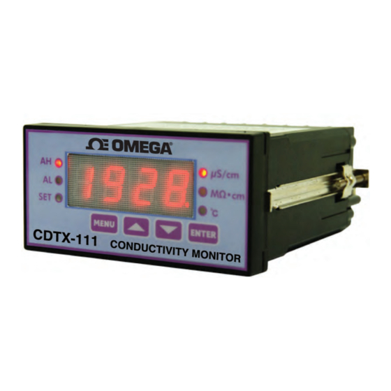
CDTX-111
Conductivity Monitor
Table of
Contents
Previous
Page
Next
Page
1
2
3
4
5
Advertisement
Table of Contents
Need help?
Do you have a question about the CDTX-111 and is the answer not in the manual?
Ask a question
Questions and answers
Related Manuals for Omega CDTX-111
Monitor Omega CDTX-112 User Manual
Conductivity monitor (24 pages)
Monitor Omega ILD24-UTP User Manual
Big display, universal temperature & process controller (72 pages)
Monitor Omega DP2000-M User Manual
Rtd process monitor with 1° resolution (32 pages)
Monitor Omega FPD3100-D Series User Manual
12mm lc digital with analog output options (21 pages)
Monitor Omega iLD Big Display User Manual
Big display universal strain & process (56 pages)
Monitor Omega iDR Quick Start
I series, monitor, limit alarm din rail temperature & process (2 pages)
Monitor Omega DP2000-K User Manual
Thermocouple process monitor (36 pages)
This manual is also suitable for:
Cdtx-112
Table of Contents
Print
Rename the bookmark
Delete bookmark?
Delete from my manuals?
Login
Sign In
OR
Sign in with Facebook
Sign in with Google
Upload manual
Upload from disk
Upload from URL


Need help?
Do you have a question about the CDTX-111 and is the answer not in the manual?
Questions and answers