
Related Manuals for Omega Engineering SP-001


Summary of Contents for Omega Engineering SP-001
- Page 1 User’s Guide Shop online at omega.com e-mail: info@omega.com For latest product manuals: www.omegamanual.info SP-001, SP-002 Ultra Miniature IR Smart Probe...
- Page 2 Servicing North America: U.S.A. Omega Engineering, Inc. Headquarters: 800 Connecticut Ave. Suite 5N01, Norwalk, CT 06854 Toll-Free: 1-800-826-6342 (USA & Canada only) Customer Service: 1-800-622-2378 (USA & Canada only) Engineering Service: 1-800-872-9436 (USA & Canada only) Tel: (203) 359-1660 Fax: (203) 359-7700 e-mail: info@omega.com...
-
Page 3: Table Of Contents
Table of Contents Notes Warnings, and Cautions ..................4 Introduction ........................5 Description ........................ 5 Included with Your SP-001 / SP-002 ................5 Additional Material Needed ..................5 Optional Materials ....................5 Manuals / Software ....................5 Input / Output Pin Layout ....................6 Optical Chart ........................ -
Page 4: Notes Warnings, And Cautions
/ or damage to your equipment. The following labels identify information that is especially important to note: Note: Provides you with information that is important to successfully setup and use the SP-001. Caution or Warning: Tells you about the risk of electrical shock. -
Page 5: Introduction
We’ve integrated an advanced suite of IIoT centric featured electronics called Smart Core. These features enable plug and play connectivity, fully featured alarms and notifications, data assurance, and data storage of up to 1499 sensor readings. Included with Your SP-001 / SP-002 •... -
Page 6: Input / Output Pin Layout
The optical chart below indicates the nominal target spot diameter at any given distance from the sensing head and assumes 90% energy. Figure 3 reflects the SP-001 with a field of view of 6:1. Figure 4 reflects the SP-002 with a field of view of 10:1. -
Page 7: Preparation
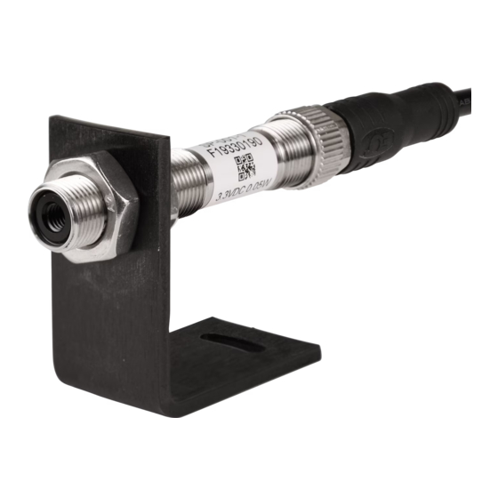
The sensor should be mounted so that the measured spot size is smaller than the target. Note: A mounting bracket for the SP-001 / SP-002 is sold separately. Ambient Temperature The sensor is designed to operate in ambient temperatures from -40°C to 85°C (-40°F to 185°F). -
Page 8: Mechanical Installation
The SP-001 / SP-002 requires a Smart Interface (IF-001-0) or Wireless Transmitter to connect to your computer. Locate the position of the keyway as a guide on the SP-001 / SP-002 prior to making the connection. See Figure 6. Figure 6 The sensor can be mounted on brackets, clamps or cutouts of your own design or you can use the fixed and adjustable Omega mounting bracket accessory: SP-001-MB. -
Page 9: Communication Interface
Figure 10 Communication Interface • Connection Type: Select the type of connection you have between your SP-001 / SP-002 and your computer. USB connection is displayed in Figure 9. USB Serial connection is displayed in Figure 10. • Command Timeout: The maximum time (in milliseconds) for a command to be completed before the command is aborted. -
Page 10: Setting Emissivity
Emissivity Dropdown and click Apply Settings to finalize. See Figure 11. Setting Emissivity via Secondary Temperature Device Note: Ensure the SP-001 / SP-002 is connected to Omega Sync and pointed at the material being measured at a distance that covers the entire field of view. Step 1: Click Calibration. -
Page 11: Adjusting Spike And Noise Suppression
Step 3: Once the target temperature has been determined, enter the target temperature into Omega Sync. See Figure 13. Figure 13 Step 4: Click Calibrate to set the emissivity changed and exit out of the calibration pop-up. Click Apply Settings to finalize. Note: When you click Calibrate, the emissivity value in Figure 11 will change according to the value of the Target Surface Temperature entered. -
Page 12: Alarm Setting
Alarm Setting The SP-001 offers software adjustable alarms for your smart sensor. To begin alarm setup, follow these instructions. Step 1: Click the icon next to the input you would like to customize. Figure 15 Step 2: Customize alarm settings to your satisfaction. See Figure 16. -
Page 13: Appendix A - Emissivity Table
Appendix A - Emissivity Table Material Emissivity (ε) Aluminum – pure highly polished plate ......0.04 to 0.06 Aluminum –... - Page 14 Material Emissivity (ε) Asbestos Board..........0.96 Asphalt, tar, pitch.
-
Page 15: Specifications
Accuracy Over Entire Ambient Operating Range: 4°C (3.6 °F) or 3% of reading, whichever is greater Repeatability: 1°C (1.8°F) or 1% of reading Field of View: SP-001 is 6:1 SP-002 is 10:1 Spectral Response: 5.5 to 14 microns Emissivity: 0.01 to 1.00, software adjustable... - Page 16 OMEGA is a trademark of OMEGA ENGINEERING, INC. © Copyright 2019 OMEGA ENGINEERING, INC. All rights reserved. This document may not be copied, photocopied, reproduced, translated, or reduced to any electronic medium or machine-readable form, in whole or in part, without the...
- Page 17 Where Do I Find Everything I Need for Process Measurement and Control? OMEGA…Of Course! Shop online at omega.com TEMPERATURE M U Thermocouple, RTD & Thermistor Probes, Connectors, Panels & Assemblies M U Wire: Thermocouple, RTD & Thermistor M U Calibrators & Ice Point References M U Recorders, Controllers &...
Need help?
Do you have a question about the SP-001 and is the answer not in the manual?
Questions and answers