
Related Manuals for Omega Engineering FMA-1600A Series


Summary of Contents for Omega Engineering FMA-1600A Series
- Page 1 User’s Guide Shop online at omega.com e-mail: info@omega.com For latest product manuals: www.omegamanual.info FMA-1600A Series Mass Flow Meters...
- Page 2 Servicing North America: U.S.A. Omega Engineering, Inc. Headquarters: Toll-Free: 1-800-826-6342 (USA & Canada only) Customer Service: 1-800-622-2378 (USA & Canada only) Engineering Service: 1-800-872-9436 (USA & Canada only) Tel: (203) 359-1660 Fax: (203) 359-7700 e-mail: info@omega.com For Other Locations Visit omega.com/worldwide The information contained in this document is believed to be correct, but OMEGA accepts no liability for any errors it contains, and reserves the right to alter specifications without notice.
- Page 3 Thank you for purchasing a FMA-1600A Series Gas Flow Meter. Please take the time to find and read the information contained in this manual. This will help to ensure that you get the best possible service from your instrument. This manual covers the following Omega instruments:...
-
Page 4: Table Of Contents
TABLE OF CONTENTS Page GETTING STARTED MOUNTING PLUMBING PRESSURE POWER AND SIGNAL CONNECTIONS INPUT SIGNALS Analog Input Signal RS232 / RS485 Digital Input Signal OUTPUT SIGNALS RS232 / RS485 Digital Output Signal Standard Voltage (0-5 Vdc) Output Signal Optional 0-10 Vdc Output Signal Optional Current (4-20 mA) Output Signal Optional 2nd Analog Output Signal Information for Omega TFT (Color Display) Instruments... - Page 5 TABLE OF CONTENTS Page RS232 or RS485 Output and Input Configuring HyperTerminal® Streaming Mode Tareing via RS232 or RS485 Changing from Streaming to Polling Mode Gas Select Creating and Deleting Gas Mixtures using RS232 or RS485 Collecting Data Data Format Sending a Simple Script File to HyperTerminal®...
-
Page 6: Getting Started
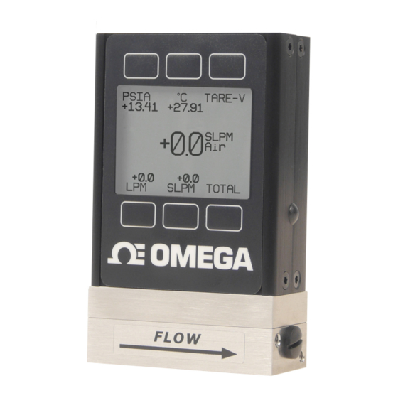
GETTING STARTED Power Jack 8 Pin Mini-DIN Display Screen Inlet Connection Port Outlet Connection Port Flow Direction Arrow Medium Mass Flow Meter MOUNTING FMA-1600A Gas Flow Meters have holes on the bottom for mounting to flat panels. See pages 51-65. FMA-1600A Meters can usually be mounted in any position. -
Page 7: Pressure
We recommend the use of in-line sintered filters to prevent large particulates from entering the measurement head of the instrument. Suggested maximum particulate sizes are as follows: 5 microns for units with FS flow ranges of 0-1 sccm or less. 20 microns for units with FS flow ranges between 0-2 sccm and 0-1 slpm. -
Page 8: Power And Signal Connections
POWER AND SIGNAL CONNECTIONS Power can be supplied to your meter through either the power jack or the 8 pin Mini-DIN connector. An AC to DC adapter which converts line AC power to DC voltage and current as specified below is required to use the power jack. Meters require a 7-30 Vdc power supply with a 2.1 mm female positive center plug capable of supplying at least 100mA. -
Page 9: Input Signals
INPUT SIGNALS Analog Input Signal Apply analog input to Pin 4 as shown on page 8. For DB15 Pin-outs, see pages 67 to 73. Standard 0-5 Vdc is the standard analog input signal. Apply the 0-5 Vdc input signal to pin 4, with common ground on pin 8. Optional 0-10 Vdc: If specified at time of order, a 0-10 Vdc input signal can be applied to pin 4, with common ground on pin 8. -
Page 10: Rs232 / Rs485 Digital Input Signal
RS232 / RS485 Digital Input Signal To use the RS232 or RS485 input signal, connect the RS232 / RS485 Output Signal (Pin 5), the RS232 / RS485 Input Signal (Pin 3), and Ground (Pin 8) to your computer serial port as shown below. (See page 26 for details on accessing RS232 / RS485 input.) ... -
Page 11: Output Signals
OUTPUT SIGNALS RS232 / RS485 Digital Output Signal To use the RS232 or RS485 output signal, it is necessary to connect the RS232 / RS485 Output Signal (Pin 5), the RS232 / RS485 Input Signal (Pin 3), and Ground (Pin 8) to your computer serial port as shown on page 8. (See page 26 for details on accessing RS232 / RS485 output.) Standard Voltage (0-5 Vdc) Output Signal FMA-1600A flow meters equipped with a 0-5 Vdc (optional 0-10 Vdc) will... - Page 12 CAUTION! Do not connect this device to “loop powered’” systems, as this will destroy portions of the circuitry and void the warranty. If you must interface with existing loop powered systems, always use a signal isolator and a separate power supply. Purple (Ground) Yellow Unit A...
-
Page 13: Information For Omega Tft (Color Display) Instruments
Information for Omega TFT (Color Display) Instruments Omega TFT (color display) instruments have a high contrast back-lit LCD display. TFT instruments operate in accordance with Omega standard operating instructions for our monochrome menus and displays with the following differences. Multi-Color Display Color Codes: GREEN: Green labels identify the parameters and/or adjustments associated with the button directly above or below the label. -
Page 14: Displays And Menus
DISPLAYS AND MENUS The device screen defaults to Main display as soon as power is applied to the meter. Main The Main display shows pressure, temperature, volumetric flow and mass flow. TARE V PSIA +13.60 +21.50 Pressing the button adjacent to a +0.00 parameter will make that parameter SCCM... -
Page 15: Main
MAIN This mode defaults on power up, with mass flow as the primary displayed parameter. The following parameters are displayed in TARE V PSIA +21.50 +13.60 the Main mode. Gas Absolute Pressure: This sensor +0.00 SCCM references hard vacuum and reads Mass Flow incoming pressure both above and below local atmospheric pressure. -
Page 16: Volumetric Flow Rate
before pressing the TARE button. If the unit reads a significant negative value when removed from the line and blocked, it was given a false zero. It is better to zero the unit at atmospheric pressure and a confirmed no flow condition than to give it a false zero under line pressure. -
Page 17: Select Menu
SELECT MENU From Select Menu you can change the selected gas, interact with your RS232 / RS485 settings or read manufacturer’s data. Press the button next to the desired operation to bring that function to the screen. MODEL INFO OMEGA Ph 800-826-6342 MISC1 MISC2 UNIT ID... -
Page 18: Gas Select
GAS SELECT Gas Select allows you to set your device to up to 150 standard gases and mixes. You can also use Composer to program and store up to 20 additional DOWN PAGE gas mixes. >Recent Standard Gas Select is accessed by pressing the Factory Custom button below GAS SELECT on the Select Composer User Mixes... -
Page 19: Composer
COMPOSER Composer allows you to program and save up to 20 custom gas mixes containing 2 to 5 component gases found in the gas lists (pages 33-40). The DOWN minimum resolution is 0.01%. >Add Mix: 20 Free Composer is accessed by selecting Composer User Mixes on the GAS SELECT display. - Page 20 DOWN SELECT DOWN SELECT DIGIT DIGIT Percent of Air: Percent of Ar Argon: 50.00 30.00 ˄ ˄ BACK/ BACK/ CANCEL CLEAR CANCEL CLEAR DOWN SELECT EDIT ADD GAS DIGIT NAME OPTNS Percent of He Helium: Composer Mix: MyGAS 50% Air 20.00 30% AR Argon ˄...
-
Page 21: Communication Select
COMMUNICATION SELECT Access Communication Select by pressing the button above RS232 COMM or RS485 COMM on the Select Menu display. Unit ID – Valid unit identifiers are the UNIT ID BAUD 19200 letters A-Z and @. The identifier allows you to assign a unique address to each device so that multiple units can be connected to a single RS232 or RS485 computer port. -
Page 22: Miscellaneous
MISCELLANEOUS Miscellaneous is accessed by pressing the MISC button on the Select Menu display. Next select either MISC1 or MISC2. MISC1 will display as shown at left. ZERO BAND refers to Display Zero Deadband. Zero deadband is a value below which the display ZERO PRESS FLOW... -
Page 23: Misc2
MISC2 will display as shown at left. STP/NPT refers to the functions that allow your selection of standard temperature and pressure conditions or normal temperature STP/ DIAG ROTATE TEST DISP and pressure conditions. This feature is generally useful for comparison purposes to other devices or systems using different STP parameters. -
Page 24: Diag Test
DIAG TEST: This diagnostic screen displays the current internal register values, which is useful for noting factory settings prior to making any changes. It is also helpful SCROLL for troubleshooting with Omega customer R8: AP Sig 7871 R9: Temp Sig 39071 service personnel. -
Page 25: Manufacturer Data
MANUFACTURER DATA Manufacturer Data is accessed by pressing the MFG DATA button on the Select Menu display. The initial display shows the name and MODEL INFO telephone number of the manufacturer. OMEGA Press MODEL INFO to show important information about your flow meter Ph 800-826-6342 including the model number, serial Fax 203-359-7700... -
Page 26: Rs232 Or Rs485 Output And Input
RS232 / RS485 Output and Input Configuring HyperTerminal®: Open your HyperTerminal® RS232 / RS485 terminal program (installed under the “Accessories” menu on all Microsoft Windows® operating systems). 2. Select “Properties” from the file menu. Click on the “Configure” button under the “Connect To” tab. Be sure the program is set for: 19,200 baud (or matches the baud rate selected in the RS232 / RS485 communications menu on the meter) and an 8-N-1-None (8 Data Bits, No Parity, 1 Stop Bit, and no Flow Control) protocol. -
Page 27: Tareing Via Rs232 Or Rs485
Tareing via RS232 / RS485: Tare –Tareing (or zeroing) the flow meter provides it with a reference point for zero flow. This is a simple but important step in obtaining accurate measurements. It is good practice to “zero” the flow meter each time it is powered up. A unit may be Tared by following the instructions on page 10 or it may be Tared via RS232 / RS485 input. -
Page 28: Gas Select
Gas Select – The selected gas can be changed via RS232 / RS485 input. To change the selected gas, enter the following commands: In Polling Mode: Address$$#<Enter> (e.g. B$$#<Enter>) Where # is the number of the gas selected from the table below. Note that this also corresponds to the gas select menu on the flow meter screen (the Standard gas category is shown in the example below): Argon... -
Page 29: Creating And Deleting Gas Mixtures Using Rs232 Or Rs485
Creating and Deleting Gas Mixtures with Composer using RS232 or RS485 Note: All commands must be prefixed with the unit ID letter. The unit should not be in streaming mode. You may create and store up to 20 gas mixtures containing up to five constituent gases each. -
Page 30: Collecting Data
Collecting Data: The RS232/RS485 output updates to the screen many times per second. Very short- term events can be captured simply by disconnecting (there are two telephone symbol icons at the top of the HyperTerminal® screen for disconnecting and connecting) immediately after the event in question. The scroll bar can be driven up to the event and all of the data associated with the event can be selected, copied, and pasted into Microsoft®... -
Page 31: Sending A Simple Script File To Hyperterminal
Sending a Simple Script File to HyperTerminal® It is sometimes desirable to capture data for an extended period of time. Standard streaming mode information is useful for short term events, however, when capturing data for an extended period of time, the amount of data and thus the file size can become too large very quickly. -
Page 32: Operating Principle
14. The “Line Delay” box is defaulted to 0 milliseconds. This is where you will tell the program how often to read a line from the script file you’ve created. 1000 milliseconds is one second, so if you want a line of data every 30 seconds, you would enter 30000 into the box. -
Page 41: Supported Units List
Supported Units: This device supports many different units. You may select the desired units (see page 28). Note that only units appropriate to this device are available for selection. Pressure Units Absolute Gauge Differential Notes pascal hPaA hPaG hPaD hectopascal kPaA kPaG kPaD... -
Page 42: Temperature Units
True Mass Flow Units Label Notes mg/s milligram per second mg/m milligram per minute gram per second gram per minute gram per hour kg/m kilogram per minute kg/h kilogram per hour oz/s ounce per second oz/m ounce per minute lb/m pound per minute lb/h pound per hour... -
Page 43: Troubleshooting
TROUBLESHOOTING Display does not come on or is weak. Check power and ground connections. Please reference the technical specifications (pages 51-61) to assure you have the proper power for your model. Flow reading is approximately fixed either near zero or near full scale regardless of actual line flow. - Page 44 Flow flutters or is jumpy. The meters are very fast and will pick up any actual flow fluctuations such as from a diaphragm pump, etc. Also, inspect the inside of the upstream connection for debris such a PTFE tape shreds. Note: FMA-1600A meters feature a programmable geometric running average (GRA) that can aid in allowing a rapidly fluctuating flow to be read (see “Pressure Averaging”...
-
Page 45: Maintenance And Recalibration
Maintenance and Recalibration General: FMA-1600A Flow Meters require minimal maintenance. They have no moving parts. The single most important thing that affects the life and accuracy of these devices is the quality of the gas being measured. The meter is designed to measure CLEAN, DRY, NON-CORROSIVE gases. -
Page 46: Option: Totalizing Mode
Option: Totalizing Mode Meters and Controllers can be purchased with the Totalizing Mode option. This option adds an additional mode screen that displays the total flow (normally in the units of the main flow screen) that has passed through the device since the last time the totalizer was cleared. -
Page 47: Option: Portable Meters
Omega Portable Meters and Gauges Omega Rechargeable Flow Meters and Pressure Gauges use a Li-Ion 3.7V cell located in the top section of the device. The Li-Ion cell must not be removed. Normal battery life of a fully-charged cell is 18 hours with a monochrome display or 5 hours with a TFT color display, when the backlight is set to 10. -
Page 48: Pressure Menu For Portable Meters
Pressure Menu for Portable Meters Omega portable meters are programmed with additional pressure read options. Pressing the pressure button once (upper left) will move the pressure reading to the main display. Pressing the button a second time will open a menu of pressure read options. -
Page 49: Accessory: Multi-Drop Box
Accessory: FMA1600-MDB Multi-Drop Box The FMA1600-MDB Multi-Drop Box makes it convenient to wire multiple flow and/or pressure devices to a single RS232 or RS485 port. Now available with a USB interface! The Multi-Drop Box has nine 8 pin mini-DIN ports available. The ports are to be used with a standard double ended 8 pin mini-DIN (DC-62) style cable going from the box to each flow or pressure device. -
Page 50: Accessories
Accessories Part Number Description 8 Pin Male Mini-DIN connector cable, single ended, FMA1600-C1 6 foot length 8 Pin Male Mini-DIN connector cable, double ended, FMA1600-C2 6 foot length 8 Pin Male Mini-DIN to DB9 Female Adapter, 6 foot FMA1600-C3 length Universal 100-240 VAC to 24 Volt DC Power Supply FMA1600-PSU Adapter... -
Page 51: Fma-1600A Technical Specifications
Technical Data for FMA-1600A Mass Flow Meters 0 to 0.5 sccm Full Scale through 0 to 5000 slpm Full Scale Standard Operating Specifications (Contact Omega for available options) Performance FMA-1600A Mass Flow Meter Accuracy at calibration conditions ± (0.8% of Reading + 0.2% of Full Scale) after tare High Accuracy at calibration conditions ±... -
Page 52: Fma-Lp1600A Technical Information
26.67mm 1.050in 98.98mm 3.897in [8.53mm] [8.53mm] .336in .336in 60.33mm [13.34mm] [13.34mm] 2.375in .525in M5X0.8 (10-32 UNF) .525in Both Sides 56.52mm 3.175mm 2.225in FMA-1600A 3.81mm .125in 0 – 0.5 sccm .150in 0 – 1 sccm 0 – 2 sccm 23.495mm 0 – 5 sccm .925in 0 –... - Page 53 FMA-1600A 40.64mm 0 – 50 slpm 1.600in 0 – 100 slpm 110.92mm 4.367in 12.70mm 12.70mm .500in .500in 1/4 NPT 20.32mm Both sides 101.60mm 20.32mm .800in 4.000in .800in 82.55mm 3.250in 4.45mm 19.05mm .175in .750in 36.20mm 1.425in 4X 8-32 UNC .375in[9.53mm] 50 slpm to 100 slpm approximate shipping weight: 2.4 lb. DATE 1/4/2016 REV.
- Page 54 FMA-1600A 0 – 500 slpm 40.64mm 0 – 1000 slpm 1.600in 0 – 1500 slpm 126.16mm 4.967in 20.32mm 20.320mm .800in .800in 3/4 NPT Both sides 20.32mm 20.320mm 101.60mm .800in .800in 4.000in 82.55mm 3.250in 4.45mm 19.05mm .175in .750in 36.20mm 1.425in 4X 8-32 UNC .375in[9.53mm] 500 slpm to 1500 slpm approximate shipping weight: 3.5 lb DATE...
- Page 55 73.66mm 2.900in 134.29mm 5.287in 24.38mm 24.38mm .960in .960in 132.08mm 36.83mm 1-1/4 NPT" 36.83mm 5.200in 1.450in Both Sides 1.450in 34.29mm 1.350in 5.08mm .200in 68.58mm 2.700in FMA-1600A 0 – 3000 slpm 97.79mm 8-32 UNC .330in[8.382mm] 3.850in DATE 1/4/2016 REV. M-3000SLPM-D-MSPEC 3000 slpm approximate shipping weight: 4.5 lb 132.08mm FMA-1600A 5.200in...
- Page 56 FMA-1600A 0 – 5000 slpm 5000 slpm approximate shipping weight:14 lb ...
- Page 57 Technical Data for FMA-LP1600A Low Pressure Drop Mass Flow Meters 0 to 0.5 sccm Full Scale through 0 to 500 slpm Full Scale Standard Operating Specifications (Contact Omega for available options.) Performance FMA-LP1600A Mass Flow Meter Accuracy at calibration conditions ±...
- Page 58 FMA-LP1600A 0 – 0.5 sccm 26.67mm 0 – 1 sccm 1.050in 0 – 2 sccm 0 – 5 sccm 0 – 10 sccm 0 – 20 sccm 98.98mm 3.897in 8.534mm 8.534mm .336in .336in 60.33mm 13.335mm 13.335mm M5X0.8 (10-32 UNF) 2.375in .525in .525in Both Sides...
- Page 59 FMA-LP1600A 0 – 10 slpm 26.67mm 1.050in 106.86mm 4.207in 9.09mm 9.09mm .358in .358in 1/4 NPT 66.68mm Both Sides 13.34mm 2.625in .525in 13.34mm .525in 59.69mm 2.350in 6.99mm 3.18mm .275in .125in 23.50mm .925in DATE 12/12/2015 2X 8-32 UNC .350in 8.89mm REV. MW-10SLPM-D-MSPEC 10 slpm approximate shipping weight: 1.4 lb.
- Page 60 FMA-LP1600A 0 – 40 slpm 40.64mm 0 – 50 slpm 1.600in 0 – 100 slpm 0 – 250 slpm 126.16mm 4.967in 20.32mm 20.32mm .800in .800in 1/2 NPT Both Sides 101.60mm 20.32mm 20.32mm 4.0000in .800in .800in 82.55mm 3.250in 19.05mm 4.45mm .750in .175in 36.20mm 1.425in...
-
Page 61: Fma-1600A-Lss Technical Information
Technical Data for FMA-1600A-LSS Mass Flow Meters FMA-1600A-LSS instruments are built for use with aggressive gases. For the most part, these instruments maintain the specifications of equivalently ranged FMA-1600A devices. Standard Compatible Gas List for FMA-1600A-LSS Meters 98% Ar / 2% CO2 Argon 75% CO2 / 25% Ar C-75... - Page 62 FMA-1600A-LSS 0 – 0.5 sccm 26.67mm 0 – 1 sccm 1.050in 0 – 2 sccm 0 – 5 sccm 0 – 10 sccm 0 – 20 sccm 0 – 50 sccm 111.68mm 4.397in 8.53mm 8.53mm .336in .336in 60.33mm 13.34mm M5X0.8 (10-32 UNF) 2.375in 13.34mm .525in...
- Page 63 FMA-1600A-LSS 0 – 50 slpm 40.64mm 0 – 100 slpm 1.600in 128.70mm 5.067in 12.70mm 12.70mm .500in .500in 1/4 NPT 101.60mm Both Sides 20.32mm 20.32mm 4.000in .800in .800in 82.55mm 3.250in 19.05mm 36.20mm .750in 1.425in 4.45mm .175in 4X8-32 UNC .375in[9.53mm] DATE 1/11/2016 50 slpm to 100 slpm approximate shipping weight: 2.4 lb.
- Page 64 FMA-1600A-LSS 0 – 500 slpm 40.64mm 0 – 1000 slpm 1.600in 0 – 1500 slpm 143.94mm 5.667in 20.32mm 20.32mm .800in .800in 20.32mm 3/4 NPT 101.60mm 20.32mm .800in Both Sides 4.000in .800in 82.55mm 3.250in 19.05mm .750in 4.45mm .175in 36.20mm 1.425in 4X8-32 UNC .375in[9.53mm] DATE 1/8/2016...
- Page 65 FMA-1600A-LSS 0 – 3000 slpm 73.66mm 2.900in 152.07mm 5.987in 24.38mm 24.38mm .960in .960in 132.08mm 36.83mm 36.83mm 5.200in 1.450in 1.450in 1.484in[37.69mm] .700in[17.78mm] 97.79mm 1-1/4 NPT 3.850in 34.29mm 5.08mm 1.350in .200in 68.58mm 2.700in 4X 8-32 UNC .330in[8.38mm] DATE 1/8/2016 REV. MS-3000SLPM-D-MSPEC 3000 slpm approximate shipping weight: 4.5 lb FMA-1600A-LSS 132.08mm 0 –...
-
Page 66: Eight Pin Mini-Din Pin-Out
Eight Pin Mini-DIN Connector Pin-Outs If your FMA-1600A Instrument was ordered with the standard Eight Pin Mini-DIN connection, please be sure to reference the following pin-out diagram. Standard 8 Pin Mini-DIN Pin-Out Mini-DIN Pin Function cable color... -
Page 67: Db15 Pin-Out Diagrams
DB15 Pin-Outs If your instrument was ordered with a DB15 connection, be sure to check the Calibration Label on the device and reference the appropriate pin-out diagram. The following pin-out chart describes the safest and generally compatible arrangement when connecting a non-FMA-1600A DB15 wire to a DB15 equipped FMA-1600A. Not all features may be available between brands, but the common denominators are featured in our DB15 offerings, along with some options for customization. - Page 68 DB15 Pin-Outs If your instrument was ordered with a DB15 connection, be sure to check the Calibration Label on the device and reference the appropriate pin-out diagram. The following pin-out chart describes the safest and generally compatible arrangement when connecting a non-FMA-1600A DB15 wire to a DB15A equipped FMA-1600A. Not all features may be available between brands, but the common denominators are featured in our DB15 offerings, along with some options for customization.
- Page 69 DB15 Pin-Outs If your instrument was ordered with a DB15 connection, be sure to check the Calibration Label on the device and reference the appropriate pin-out diagram. The following pin-out chart describes the safest and generally compatible arrangement when connecting a non-FMA-1600A DB15 wire to a DB15B equipped FMA-1600A. Not all features may be available between brands, but the common denominators are featured in our DB15 offerings, along with some options for customization.
- Page 70 DB15 Pin-Outs If your instrument was ordered with a DB15 connection, be sure to check the Calibration Label on the device and reference the appropriate pin-out diagram. The following pin-out chart describes the safest and generally compatible arrangement when connecting a non-FMA-1600A DB15 wire to a DB15B equipped FMA-1600A. Not all features may be available between brands, but the common denominators are featured in our DB15 offerings, along with some options for customization.
- Page 71 DB15 Pin-Outs If your instrument was ordered with a DB15 connection, be sure to check the Calibration Label on the device and reference the appropriate pin-out diagram. The following pin-out chart describes the safest and generally compatible arrangement when connecting a non-FMA-1600A DB15 wire to a DB15B equipped FMA-1600A. Not all features may be available between brands, but the common denominators are featured in our DB15 offerings, along with some options for customization.
- Page 72 Calibration Label on the device and reference the appropriate pin-out diagram. The following pin-out chart describes the safest and generally compatible arrangement when connecting a non-FMA-1600A Series DB15 wire to a DB15O equipped FMA-1600A Series. Not all features may be available between brands, but the common denominators are featured in our DB15 offerings, along with some options for customization.
- Page 73 DB15 Pin-Outs If your instrument was ordered with a DB15 connection, be sure to check the Calibration Label on the device and reference the appropriate pin-out diagram. The following pin-out chart describes the safest and generally compatible arrangement when connecting a non-FMA-1600A DB15 wire to a DB15B equipped FMA-1600A. Not all features may be available between brands, but the common denominators are featured in our DB15 offerings, along with some options for customization.
- Page 75 OMEGA is a trademark of OMEGA ENGINEERING, INC. © Copyright 2018 OMEGA ENGINEERING, INC. All rights reserved. This document may not be copied, photocopied, reproduced, translated, or reduced to any electronic medium or machine-readable form, in whole or in part, without...
- Page 76 Where Do I Find Everything I Need for Process Measurement and Control? OMEGA…Of Course! Shop online at omega.com TEMPERATURE M U Thermocouple, RTD & Thermistor Probes, Connectors, Panels & Assemblies M U Wire: Thermocouple, RTD & Thermistor M U Calibrators & Ice Point References M U Recorders, Controllers &...
Need help?
Do you have a question about the FMA-1600A Series and is the answer not in the manual?
Questions and answers