
Subscribe to Our Youtube Channel
Related Manuals for GarageAce ET30


Summary of Contents for GarageAce ET30
- Page 1 Instruction Manual ET30 Rolling garage door opener INSTALLATION INSTRUCTIONS | OWNERS COPY...
- Page 2 WARNING: It is vital for the safety of persons to follow all instructions. Failure to comply with the installation instructions and the safety warnings may result in serious personal injury and/or property and opener damage. Please save these instructions for future reference.
-
Page 3: Table Of Contents
TABLE OF CONTENTS 1. Safety warnings – Pages 4-5 2. Product Features – Page 6 3. Installation instructions – Pages 7-8 4. Setting and operating – Page 9-15 5. Packing list – Page 15 6. Technical data – Page 15 7. -
Page 4: Safety Warnings - Pages
1. SAFETY WARNINGS Warning — It is vital for the safety of persons to follow all instructions. Failure to comply with the following safety rules may result in serious personal injury and/or property damage. Do not operate the garage door operator unless the garage door is in full view and free from objects such as cars and children/people. - Page 5 Connect the garage door operator to a properly earthed general purpose 240V mains power outlet installed by a qualified electrical contractor. The outlet (and operator) must be positioned so that it is easily accessible. Disconnect the power cord from mains power before making any repairs or removing covers. Only experienced service person can remove covers from garage door operator.
-
Page 6: Product Features
2. PRODUCT FEATURES 1. Easy to use. Just press the remote control button or the O/S/D button on the motor to open, stop or close the roller shutter. 2. Safe and reliable remote control system featuring rolling code, low coincident code rate. 3. -
Page 7: Installation Instructions - Pages
3. Installation instructions IMPORTANT SAFETY INSTRUCTIONS FOR INSTALLATION Warning:Incorrect installation can lead to severe injury. Follow this installation instruction. SIDE ROOM REQUIREMENTS Fig. 1 shows the minimum and recommended side room. The distance between the edge of the door curtain and the inside of the bracket must be at least 40mm. - Page 8 PLEASE NOTE: THE INSTRUCTIONS FOR FIXING THE OPERATOR TO THE DOOR ARE FOR RIGHT HAND INSTALLATIONS ONLY. Installation process (FIG. 3, FIG. 4, and FIG. 5) 1. Check that the door shaft U bolt is securely tightened on the left hand side of the door. 2.
-
Page 9: Setting And Operating
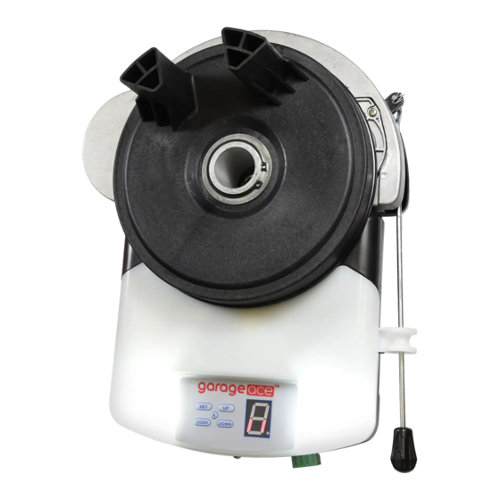
4. Setting and operating 1. O/S/C button 2. PB/GND/PE/+24V terminal 3. Manual release lever 4. Battery backup terminal 5. Programming panel 6. K button( same function as O/S/C button) H. Hole for battery backup connection... - Page 10 4.1 Left/right installation setting WARNING: This step must be completed prior to setting travel limits (4.2) if utilizing a lift sided installation. If utilizing the standard right sided installation this step can be ignored. Press ‘SET’ button and hold on until LED displays figure ‘5’, press ‘UP’ or ‘DOWN’ button to choose ‘1’ left installation or ‘0’...
- Page 11 4.2 Door travel limit Setting 4.2.1 Pull down the manual release lever, the door operator is under manual mode. 4.2.2 Open the door by hand until the door touches the upper door stop. (see Fig.7) Close the door by hand until the door touches the ground .
- Page 12 4.2.5 Press the RED O/S/C button at the bottom of door operator or K button (FIG.9), confirm the up limit and down limit are correct. If not, please re-set the travel limit according to above processes until the limits are correct.
- Page 13 4.4 Safety reverse force adjustment 4.4.1 Press ‘SET’ button and hold on until the LED displays figure ’3’. Press ‘UP’ button to increase the force, Press ‘DOWN’ button to decrease the force. The maximum force is 9, the minimum force is 1. The default is 3. Display from ‘1’...
- Page 14 Please confirm the photocells are well connection and programmed. Please check if the door will be automatically reversed when encountering an obstacle during door closing. 4.5.3 Canceling the photocell function: Press ‘DOWN’ button and hold on until the LED displays ‘H’ , press ‘DOWN’ button the LED displays 11’, to cancel this function, press ‘SET’...
-
Page 15: Packing List
4.7 Battery backup connection: It must use 24V DC 3.5Ah sealed lead acid battery. Please open the light cover to connect the wires of battery with the battery backup terminal in the control board(Fig.12). The ‘H’ of Fig.11 is a hole for battery connection wires to through. -
Page 16: Common Trouble Shooting
7. COMMON TROUBLE SHOOTING Symptom Possible reason Solution Main power not switch on Switch on the main power The door does not move Remove the barrier The door is locked or motor Unlock the door jammed The door is obstructed Check the motor is turning The door won’t reverse when The moving force of the motor is set... - Page 17 The door is beyond the original up Reset the limit position as per The door can’t fully close limit setting after power failure instruction A noise emits from the motor The up/down limit position during the first manual travel This is normal, no action required confirmation limit setting The door can only open, cannot...
-
Page 18: Final Note
Final notes This manual is only used by those who are qualified to carry out the installation. No given information in this manual can be considered of any interest to the end user. It is important for the installer to show their clients correct operation using of the opener including the using of manual disengagement cord.
Need help?
Do you have a question about the ET30 and is the answer not in the manual?
Questions and answers