
Related Manuals for Record K 32 Z


Summary of Contents for Record K 32 Z
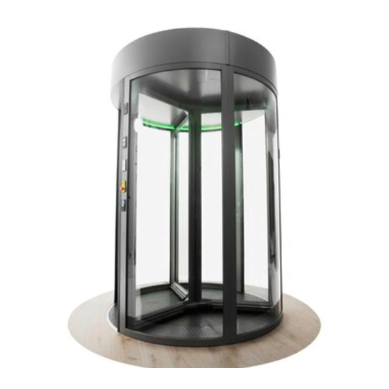
- Page 1 K 32 Z / K 42 Z User manual Your global partner for entrance solutions www.record.group...
- Page 2 Document identification Article nr.: 121-006454230 Version: Publication date: 05/07/2022 Translation of the original manual Subject to technical modifications Copyright © agtatec ag...
-
Page 3: Table Of Contents
Table of Contents Table of Contents List of changes ..............................1 Safety................................. Presentation of warning signs....................... Intended purpose of use ........................General hazards ........................... State of technology ..........................Personal protective equipment ......................Spare parts and liability ........................10 2 General information ............................11 Purpose and use of the instructions ..................... - Page 4 Table of Contents Electrical specifications of the door control KST200................26 Electrical lighting specifications ......................26 Sound pressure level ..........................27 6 Operation................................28 Operating mode symbols........................28 Instructional symbols ..........................28 Menu display............................28 Status display ............................29 Error display............................29 Operating modes selection ........................
-
Page 5: List Of Changes
List of changes List of changes Change Location Complete revision of all Sections and content Entire document New Section structure Entire document Revision of all graphics Entire document BAL_K32_K42_Z_EN_2V5_BLA_121-006454230 5 / 46... -
Page 6: Safety
Safety Safety Presentation of warning signs Various symbols are used in this guide for easier understanding: NOTICE Useful advice and information to ensure correct and efficient workflow of the system. IMPORTANT Specific details which are essential for trouble-free operation of the system. IMPORTANT Important details which must be read for proper function of the system. -
Page 7: General Hazards
Safety General hazards The following section lists hazards that can be caused by the system even when used as intended. To reduce the risk of malfunction, damage to property or injury to persons and to avoid dangerous situations, the safety instructions listed here must be observed. The specific safety instructions in the other sections of this manual must also be observed. - Page 8 Safety CAUTION Risk of material damage or injury due to unforeseen opening, closing or turning of the door! a) The door can open, close or turn unexpectedly. This may result in damage to property or injury to persons. ð No persons may be present in the opening area of the system. ð...
-
Page 9: State Of Technology
Safety DANGER Danger to life due to electric current! a) In case of contact with live parts, there is an immediate danger to life due to electric shock. Damage to or removal of the insulation or individual components can be life-threatening. ð... -
Page 10: Spare Parts And Liability
Safety The head protection serves to protect against falling and flying parts and materials. It also protects the head from bumping into hard objects. Protective goggles protect the eyes from flying parts, dust, splinters or splashes. Protective gloves are designed to protect hands from friction, abrasions, punctures or serious injury and from burning caused by contacting hot surfaces. -
Page 11: General Information
General information General information Purpose and use of the instructions These instructions are an integral part of the system and enable efficient and safe handling of the sys- tem. In order to ensure proper functioning, the instructions must be accessible at all times and kept in the immediate area of the system. -
Page 12: Definition Of Terms
General information Definition of terms Term: Explanation: System The term is also used in these instructions as a synonym for the product. Door operators, revolving doors, sliding doors, etc. are re- ferred to as a system. If information in these instructions refers to a specific type, this is shown accordingly in the text. -
Page 13: Description
Description Description Graphical display Abbreviation Description Abbreviation Description Passage width Floor ring height Passage height Cladding height Total height Total diameter Exterior diameter Interior diameter 3.1.1 Main mechanical components Abbreviation Description Drum wall Curved, fixed aluminum frame for supporting curved glass or panelling. Drum wall edge Fixed structure made of vertical frame profiling for accommodating control units. -
Page 14: Description Of The Door
Description Description of the door The door consists of two or three turnstile wings It has a microprocessor-controlled drive system, which can be used in several operating modes. The different operating modes can be selected with the corresponding BDE-D-KTA control unit. A built in error analyzer detects operating errors. -
Page 15: Legend For Safety Features And Control Elements
Description Triple winged Four winged EXTERIOR EXTERIOR INTERIOR INTERIOR Position of the turnstile wings in the locked position: Turnstile wing DKF1 = Turnstile wing 1 0° 0° DKF2 = Turnstile wing 2 120° 90° DKF3 = Turnstile wing 3 240° 180°... - Page 16 Description 15, 15A Sensors turnstile wings (OP-VSR) Horizontal heel protection safety strips (SL-FES) Foot protection sensor radial protective sliding wing Vertical light barriers drum edges Monitoring contact night shield (UW-NAS) Main power switch (UW-HAS) Control unit BDE-D-KTA Key-operated switch BDE-V Key-operated emergency switch Emergency stop switch Disabled person button...
-
Page 17: Bde-D-Kta Control Unit
Description Lighting Combination sensors Plastic manufacturer's logo System nameplate Sticker STOP Sticker Baby carriage / Wheel chair / Mother + Child / Dog Sticker Mother + Child/ Dog Sticker START Sticker Maximum weight Sticker “Opening service trap” Glass label (example) Labelling the glass surface reduces the danger of collision. -
Page 18: Information On Motion Detectors
Description 3.3.4 Information on motion detectors NOTICE Moving objects, i.e. loose poster or plants that move in the detection area can trigger an unin- tentional startup. Motion detectors are installed on each access side of the door (see “Safety and operating compon- ents legend”). -
Page 19: Options
Options Options Electromagnetic turnstile lock The door is equipped with a turnstile lock. In the LOCKED operating mode, the turnstile will lock auto- matically in the home position and will unlock when a different operating mode is selected. During a power failure, the current LOCKED or UNLOCKED state is maintained. If the turnstile is locked during a power failure, it can be manually unlocked by pulling the release knob (Bowden cable). -
Page 20: Bde-V Key Switch
Options BDE-V key switch The turnstile can be locked or unlocked with the BDE-V key switch (see Safety and operating components legend). Only a specific group of people are entitled to lock or unlock and consequently operate the door. CAUTION Danger of people being trapped inside the turnstile. -
Page 21: Start Button
Options NOTICE If the detection area of a motion detector is entered without pressing a disabled button, the turnstile will accelerate to walking speed. Start button IMPORTANT In the LOCKED mode, the start button function is disabled after 10 minutes. After pressing the start button the turnstile starts and turns one complete rotation to prevent confinement. -
Page 22: Bde-Lock Key Switch
Options BDE-Lock key switch The BDE-Lock key switch is used to lock or unlock the BDE-D-KTA control unit for the door. Only a certain people have access to this key switch. When the BDE-Lock key switch is turned to the right (locked), the door will continue in the operating mode that was preset on the BDE-D-KTA (for example, AUTOMATIC). -
Page 23: Light Switch
Options Folding positions Inside Outside Folding drum walls only for K32 Inside Outside 4.13 Light switch The lighting can be or is connected to an on-site light switch or controlled by the building control sys- tem to be switched OFF or ON. 4.14 Lighting control Depending on the configuration, the lights can either be switched ON or OFF from an external spot or... -
Page 24: Night Shield
Options 4.15 Night shield NOTICE The door is equipped with a night shield located on the exterior entrance. If it is manually pushed out of the open position while rotating, the turnstile will immediately stop for safety reasons. For safety reasons, the automatic mode only functions if the night shield is completely open. During a power failure, the status of the night shield remains LOCKED or UNLOCKED. - Page 25 Options By pressing the door open button, or using the turn key switch or on-site code card reader, the night shield will unlock and open up completely. Once the night shield is completely opened, the turnstile will start, turn one complete rotation at slow speed and come to a standstill in the home position.
-
Page 26: Specifications
Specifications Specifications Environmental conditions Temperature range From -15 to +50° C Humidity range Up to 85% rel. humidity, not condensing Electric specifications of the door Mains voltage: 230 VAC Frequency: 50-60 Hz Nominal power: max. 300 W Mains fuse: 10A circuit breaker with tripping characteristic C or K Control voltage: 24 VDC Motor voltage:... -
Page 27: Sound Pressure Level
Specifications Sound pressure level The A-weighted emission sound pressure level of the drive is less than 70 dB. LpA_<70dB (A). BAL_K32_K42_Z_EN_2V5_BLA_121-006454230 27 / 46... -
Page 28: Operation
Operation Operation Operating mode symbols Operating modes Control button Standard display symbol LOCKED UNLOCKED or SSK opening By SSK opening press the locked button 1 more time AUTOMATIC CONTINUOUS ONEWAY MANUAL 2x briefly or 1x long - press (>2s) Restart lock After reset press the info button 1x long (>2s) Emergency operation button Instructional symbols... -
Page 29: Status Display
Operation Status display The status display shows information with status number and message in plain text. If there is more than one piece of information, the number and the current entry number is also displayed. The next entry is called up by pressing the info key. Error display Current errors are displayed in the error display as a list of the error numbers without plain text display in decimal format. -
Page 30: Special Function Selection
Operation NOTICE The physical force required for manually pushing the door in the MANUAL mode is determ- ined by the size of the turnstile and the friction that occurs. The larger and heavier the turn- stile is, the more physical force is required. –... -
Page 31: Servicing And Maintenance
Servicing and maintenance Servicing and maintenance General remarks According to current legislation, the operator of an automatic door system is responsible for its main- tenance and safety. Accidents or defects can be avoided if the system operator takes good care of the system. Testing Type of test Measure... - Page 32 Servicing and maintenance Visual inspection of all – Select the MANUAL operating – The safety strips must not have safety strips mode. any mechanical damage and they must be installed correctly and – Visually inspect all safety strips. firmly over the entire length. Function test –...
-
Page 33: Cleaning And Care
Servicing and maintenance Function test key pivot – Select LOCKED mode. – The turnstile will unlock, turn one contact SSK complete rotation and lock again. possibly – Turn the key pivot contact briefly. on the ex- – Also perform in AUTOMATIC and terior –... - Page 34 Servicing and maintenance IMPORTANT The system must be kept free of dirt, leaves, snow and ice! a) In case of heavy soiling contact a professional. b) The use of road salt or gravel in front of the access areas and inside the plant must be avoided. c) It is recommended to impregnate the safety strips and sensors with a water-repellent care product.
-
Page 35: Malfunctions
Malfunctions Malfunctions Conduct during malfunctions IMPORTANT If malfunctions that endanger the safety of individuals occur, the system must be turned off. It may not be turned back on until the problem has been resolved by a professional and the danger no long exists. 8.1.1 Troubleshooting options NOTICE... -
Page 36: Status Display And Troubleshooting Bde-D-Kta
Status display and troubleshooting BDE-D-KTA The following table lists the possible status messages by their status number, together with a detailed description and information on how to correct and reset the error display. Display text i-record / Cause and effect Possible troubleshooting Internal emergency stop –... - Page 37 Malfunctions Start button 1 Stator – Door rotates permanently – Check push button (TA-SRT1_S) – Perform reset TA-SRT1 Stator active – If not successful, contact service Start button 2 Stator – Door rotates permanently – Check push button (TA-SRT2_S) – Perform reset TA-SRT2 Stator active –...
- Page 38 Malfunctions Safety edge outside – SafetyStop, Immediate stop – Remove object from safety edge, possibly drum edge (SL-TRKA) of the rotation dirt on the floor, under a heel guard SL-TRKA active – Perform reset – If not successful, contact service Horizontal safety bar ro- –...
- Page 39 Malfunctions Night shutter not open – Immediate stop of the rota- – Fully open the night shield or drum wall breakout tion – Close / reset drum wall breakout com- not closed (UW- pletely POS2_S) – Reset pivot wings UW-POS2 stator active –...
- Page 40 Malfunctions Safety bar stator inside – SafetyStop, Immediate stop – Perform reset 3 (SL-SI3) of the rotation – If not successful, contact service SL-SI3 active Safety bar stator inside – SafetyStop, Immediate stop – Perform reset 4 (SL-SI4) of the rotation –...
- Page 41 Malfunctions Test error Horizontal – ErrorStop, Immediate stop of – Perform reset light barrier Rotor blade the rotation – If not successful, contact service 2 (OP-HSR2) OP-HSR2 test error Test error flow sensor – ErrorStop, Immediate stop of – Perform reset rotor blade 1 (OP-VLS1) the rotation –...
- Page 42 Malfunctions Vertical sensor STOP – OptoStop, Immediate stop of – Remove object from the detection range rotor blade 4 (OP- the rotation of the sensor VSR42) – Check sensor for contamination, clean if VSR4_STOP active possible – Perform reset – If not successful, contact service Test error vertical –...
-
Page 43: Restarting The Door Control
Malfunctions Vertical safety bar rotor – SafetyStop, Immediate stop – Remove object from safety edge, possibly blade backwards 3 (SL- of the rotation dirt on the floor, under a heel guard VSR3.2) – Perform reset SL-VSR32 active – If not successful, contact service Horizontal safety bar ro- –... -
Page 44: Function During A Power Failure
Malfunctions Function during a power failure CAUTION Danger of people being trapped inside the turnstile. a) Bruises and contusions through from the turnstile wing. ð Visual inspection, check whether people are trapped inside. In the event of a power failure, the rotation is stopped immediately and the turnstile is then freely ro- tatable. -
Page 45: Taking Out Of Service And Disposal
Taking out of service and disposal Taking out of service and disposal Decommissioning When shutting down or taking out of service, the system is disconnected from the mains supply and any existing battery is unplugged. NOTICE After each temporary shutdown a new commissioning must be carried out. Dismantling and disposal IMPORTANT All machine parts must be sorted by type of material and disposed of according to... - Page 46 Your global partner for entrance solutions...
Need help?
Do you have a question about the K 32 Z and is the answer not in the manual?
Questions and answers