Sign In
Upload
Download
Table of Contents
Contents
Add to my manuals
Delete from my manuals
Share
URL of this page:
HTML Link:
Bookmark this page
Add
Manual will be automatically added to "My Manuals"
Print this page
×
Bookmark added
×
Added to my manuals
Manuals
Brands
Makita Manuals
Trimmer
DRT50ZJ
Instruction manual
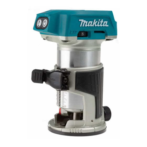
Makita DRT50ZJ Instruction Manual
Cordless trimmer
Hide thumbs
1
2
3
4
5
6
7
8
9
10
11
12
13
14
15
16
17
18
19
20
21
22
23
24
page
of
24
Go
/
24
Contents
Table of Contents
Bookmarks
Table of Contents
Specifications
Safety Warnings
Save All Warnings and Instruc- Tions for Future Reference
Functional Description
Installing or Removing Battery Cartridge
Overheat Protection
Overdischarge Protection
Overload Protection
Electronic Function
Adjusting Cutting Depth
Operation
Maintenance
Advertisement
Quick Links
Download this manual
INSTRUCTION MANUAL
Cordless Trimmer
DRT50
Read before use.
Table of
Contents
Previous
Page
Next
Page
1
2
3
4
5
Advertisement
Table of Contents
Need help?
Do you have a question about the DRT50ZJ and is the answer not in the manual?
Ask a question
Questions and answers
Related Manuals for Makita DRT50ZJ
Trimmer Makita DRT50Z Instruction Manual
Cordless trimmer (116 pages)
Trimmer Makita DRT50 Instruction Manual
Cordless trimmer (112 pages)
Trimmer Makita DRT50 Instruction Manual
Cordless trimmer (112 pages)
Trimmer Makita DRT50 Instruction Manual
Cordless trimmer (108 pages)
Trimmer Makita DRT50 Instruction Manual
18v lxt brushless cordless laminate trimmer (88 pages)
Trimmer Makita DRT50 Instruction Manual
Cordless trimmer (88 pages)
Trimmer Makita DRT50ZJX2 Instruction Manual
Cordless trimmer (88 pages)
Trimmer Makita DRT50 Instruction Manual
Cordless (88 pages)
Trimmer Makita DRT50 Instruction Manual
Cordless trimmer (88 pages)
Trimmer Makita DRT50 Instruction Manual
Cordless trimmer (76 pages)
Trimmer Makita DRT50 Instruction Manual
Cordless trimmer (56 pages)
Trimmer Makita DRT50 Instruction Manual
Cordless trimmer (32 pages)
Trimmer Makita DRT50 Instruction Manual
Cordless trimmer (25 pages)
Trimmer Makita DRT50RTJ Instruction Manual
Cordless trimmer (24 pages)
Trimmer Makita DRT50 Instruction Manual
Cordless trimmer (24 pages)
Trimmer Makita DRT50 Quick Start Manual
Cordless trimmer (4 pages)
This manual is also suitable for:
Drt50
Drt50zjx3
Drt50zx4
Table of Contents
Print
Rename the bookmark
Delete bookmark?
Delete from my manuals?
Login
Sign In
OR
Sign in with Facebook
Sign in with Google
Upload manual
Upload from disk
Upload from URL


Need help?
Do you have a question about the DRT50ZJ and is the answer not in the manual?
Questions and answers