Makita DRT50 Instruction Manual
Cordless trimmer
Hide thumbs
Also See for DRT50:
- Instruction manual (112 pages) ,
- Quick start manual (4 pages) ,
- Instruction manual (56 pages)

Related Manuals for Makita DRT50


Summary of Contents for Makita DRT50
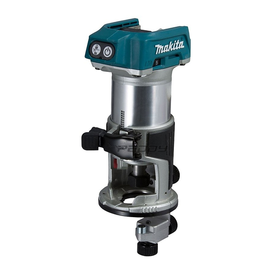
- Page 1 INSTRUCTION MANUAL Cordless Trimmer DRT50 Read before use.
-
Page 2: Specifications
SPECIFICATIONS Model: DRT50 Collet chuck capacity 6 mm, 8 mm, 1/4", or 3/8" No load speed 10,000 - 30,000 min Overall length 226 mm Rated voltage D.C. 18 V Standard battery cartridge BL1815N / BL1820 / BL1820B / BL1830 / BL1830B / BL1840 /... - Page 3 Work area safety balance at all times. Keep work area clean and well lit. Cluttered or dark areas invite accidents. Dress properly. Do not wear loose clothing or liquids, gases or dust. Power tools create sparks long hair can be caught in moving parts. which may ignite the dust or fumes.
- Page 4 Keep cutting tools sharp and clean. Properly Use clamps or another practical way to secure maintained cutting tools with sharp cutting edges and support the workpiece to a stable plat- are less likely to bind and are easier to control. form.
-
Page 5: Functional Description
If you can see the red indicator on the upper side of the button, it is not locked completely. also void the Makita warranty for the Makita tool and charger. CAUTION: Always install the battery cartridge fully until the red indicator cannot be seen. - Page 6 Indicating the remaining battery capacity When the tool or battery is overheated, the tool stops automatically and the lamp blinks. In this case, let the tool and battery cool before turning the tool on again. Only for battery cartridges with the indicator When the battery capacity is not enough, the tool stops automatically.
- Page 7 NOTICE: If the tool is not secured after closing Number Speed 10,000 min 15,000 min 20,000 min 25,000 min plunge base 30,000 min Optional accessory NOTICE: If the tool is operated continuously at loaded, resulting in tool malfunction. Select the stopper screw by rotating the stopper base.
- Page 8 Push down the tool until the tip of the trimmer bit secure the tool. 1. Stopper pole 2. Feed button turn the dial on the stopper pole so that it indicates "0". Press down the stopper pole while pressing the feed button until it contacts the stopper screw.
- Page 9 1. Shaft lock 2. Loosen 3. 4. Wrench 5. Collet nut 1. Wrench 2. Loosen 3. 4. Collet nut NOTE: position when you tighten the collet nut at the instal- ASSEMBLY original position when you start the tool. CAUTION: Always be sure that the tool is before carrying out any work on the tool.
- Page 10 base Open the lock lever of the trimmer base, then insert the tool into the trimmer base aligning the groove on the tool with the protrusion on the trimmer base. in reverse. CAUTION: When using the tool with the trim- mer base, be sure to install the dust nozzle on the trimmer base.
- Page 11 base Optional accessory Press the shaft lock, then loosen the collet nut. 1. Base plate Open the lock lever of the offset base, then insert the tool into the offset base. 1. Collet nut 2. Shaft lock 3. Wrench Remove the collet nut and the collet cone. 1.
- Page 12 1. Lock lever 1. Collet nut 2. Wrench 3. in reverse. NOTE: You can also mount the belt to the pulley with- 1. Base plate Insert the collet cone and the trimmer bit into the offset base, and then tighten the collet nut. 1.
-
Page 13: Operation
nozzle on the plunge base base Insert the dust nozzle into the plunge base so that the Optional accessory Open the lock lever of the plunge base, then insert plunge base, and then tighten the thumb screw on the the tool into the plunge base all the way aligning the tion procedure in reverse. - Page 14 Using the straight guide Optional accessory wing nut. NOTE: Before cutting on the actual workpiece, it is speed depends on the trimmer bit size, the kind of workpiece, and depth of cut. Moving the tool forward to the bit or motor. Moving the tool forward too slowly 1.
- Page 15 For cutting circles between 121 mm and 221 mm in radius. and the cutting position is too wide for the straight 1. Center hole guide, or if the side of the workpiece is not straight, the straight guide cannot be used. NOTE: Circles between 172 mm and 186 mm in piece and use it as a guide against the trimmer base.
- Page 16 Using the trimmer guide Optional accessory like veneers for furniture by moving the guide roller along the side of the workpiece. Loosen the clamp screw, then install the trimmer 1. Base plate 2. guide on the trimmer base, and then tighten the clamp screw.
- Page 17 Using the tool with the offset base such as a corner. 1. Workpiece 2. Bit 3. Guide roller Using the tool with the tilt base wing screws, then tilt the tool at the desired angle, and Using the trimmer base with the then tighten the wing screws.
- Page 18 1. Wing bolt 2. Guide holder 3. Wing nut 4. Straight guide Loosen the wing nut on the straight guide and 1. Bar type grip 2. Grip attachment be installed on the offset base instead of the bar type grip. 1.
- Page 19 Using the templet guide and the cutting position is too wide for the parallel ruler, Optional accessory or if the side of the workpiece is not straight, the parallel ruler cannot be used. Loosen the screws on the base and remove them. Place the templet guide on the base, and then tighten piece and use it as a guide against the plunge base.
-
Page 20: Maintenance
Centers, always using Makita replacement parts. OPTIONAL ACCESSORIES 1/4" CAUTION: These accessories or attachments are recommended for use with your Makita tool 1/4" accessories or attachments might present a risk of 1/4" for its stated purpose. Unit: mm If you need any assistance for more details regard- ing these accessories, ask your local Makita Service Center. - Page 21 Corner rounding bit θ 1/4" 90° Unit: mm 1/4" 1/4" Unit: mm Chamfering bit θ 1/4" Unit: mm 30° 45° 60° Unit: mm 1/4" Unit: mm 21 ENGLISH...
- Page 22 Ball bearing chamfering bit θ 45° 1/4" Unit: mm 60° Unit: mm Ball bearing beading bit 1/4" Unit: mm Ball bearing corner rounding bit Unit: mm 1/4" Unit: mm Unit: mm 22 ENGLISH...
- Page 23 Ball bearing roman ogee bit Unit: mm 23 ENGLISH...
- Page 24 Jan-Baptist Vinkstraat 2, Makita Europe N.V. 3070 Kortenberg, Belgium 3-11-8, Sumiyoshi-cho, Makita Corporation Anjo, Aichi 446-8502 Japan 885585D221 www.makita.com 20170412...
Need help?
Do you have a question about the DRT50 and is the answer not in the manual?
Questions and answers