Daikin SEHVX20BAW Installation And Operation Manual
Split packaged air-cooled water chiller
Hide thumbs
Also See for SEHVX20BAW:
- Installation and operation manual (60 pages) ,
- Installer and user reference manual (72 pages) ,
- Installer and user manual (76 pages)
Table of Contents

Related Manuals for Daikin SEHVX20BAW


Summary of Contents for Daikin SEHVX20BAW
- Page 1 Installation and operation manual Split packaged air-cooled water chiller SERHQ020BAW1 SERHQ032BAW1 SEHVX20BAW SEHVX32BAW Installation and operation manual SEHVX40BAW English Split packaged air-cooled water chiller SEHVX64BAW...
- Page 2 2PW40200-18W...
- Page 3 2PW40200-18W...
- Page 4 3PW57792-14H...
-
Page 5: Table Of Contents
Table of contents 5.7.3 To insulate the water piping ......... 18 Table of contents Connecting the electrical wiring..........18 5.8.1 Field wiring: Overview..........18 5.8.2 To route and fix the power supply........ 18 5.8.3 To connect the power supply of the outdoor unit ..19 1 About the documentation 5.8.4 To connect the power supply and transmission... -
Page 6: About The Documentation
This appliance is intended to be used by expert or trained Daikin website (publicly accessible). users in shops, in light industry and on farms, or for ▪ The full set of latest technical data is available on the Daikin commercial use by lay persons. extranet (authentication required). -
Page 7: About The Units And Options
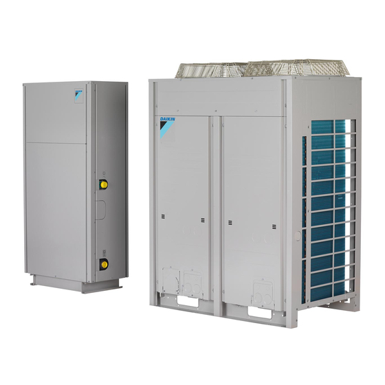
3 About the units and options Heating About the units and options Identification 3.1.1 About the outdoor unit SERHQ outdoor units are designed for outdoor installation and are meant to be combined with SEHVX indoor units. The outdoor units are designed to work in heating mode at ambient temperatures from –15°C ... -
Page 8: Installation Site Requirements Of The Indoor Unit
Outdoor unit ▪ Foreign materials inside pipes (including oils for fabrication) must be ≤30 mg/10 m. ▪ Piping connection sizes Indoor unit Liquid Outdoor unit Liquid SEHVX20BAW Ø25.4 mm Ø12.7 mm 1× SERHQ020BAW1 Ø22.2 mm Ø9.52 mm SEHVX32BAW Ø25.4 mm Ø12.7 mm 1× SERHQ032BAW1 Ø28.6 mm... -
Page 9: Preparing Electrical Wiring
4 Preparation Minimum water volume Model Minimum total water volume (l) INFORMATION In critical processes, or in rooms with a high heat load, extra water might be required. INFORMATION Water volume correction factor The temperature step difference can be modified using Temperature differential (K) settings [A‑02] and [F‑00]. -
Page 10: Installation
SERHQ032BAW1 40 A field setting components" on page 22. Indoor unit Recommended fuses 5.1.3 To open the indoor unit SEHVX20BAW 6 A DANGER: RISK OF ELECTROCUTION SEHVX32BAW 10 A SEHVX40BAW DANGER: RISK OF BURNING SEHVX64BAW To gain access to the unit, front plates need to be opened as follows: NOTICE 4×... -
Page 11: To Open The Electrical Component Box Of The Indoor Unit
5 Installation Not allowed Allowed ▪ The height of the foundation must at least be 150 mm from the floor. In heavy snowfall areas, this height should be increased, depending on the installation place and condition. ▪ The preferred installation is on a solid longitudinal foundation (steel beam frame or concrete). -
Page 12: Connecting The Refrigerant Piping
5 Installation NOTICE Connecting the refrigerant piping ▪ When the installation height of the unit needs to be increased, do NOT use stands to only support the 5.4.1 Using the stop valve and service port corners. To handle the stop valve ▪... -
Page 13: To Connect The Refrigerant Piping To The Outdoor Unit
5 Installation WARNING Take sufficient precautions in case of refrigerant leakage. If refrigerant gas leaks, ventilate the area immediately. Possible risks: ▪ Excessive refrigerant concentrations in a closed room can lead to oxygen deficiency. ▪ Toxic gas may be produced if refrigerant gas comes into contact with fire. -
Page 14: To Connect The Refrigerant Piping To The Indoor Unit
5 Installation 2 Connect a charge hose to service ports of all stop valves. 3 Recover gas and oil from the pinched piping by using a recovery unit. CAUTION Do not vent gases into the atmosphere. 4 When all gas and oil is recovered from the pinched piping, disconnect the charge hose and close the service ports. -
Page 15: Checking The Refrigerant Piping
▪ Use accessory pipes to connect field refrigerant piping to the piping connections on the indoor unit. For SEHVX20BAW, after cutting off the end of both the liquid and gas refrigerant piping, braze accessory pipe 1 to the liquid connection and accessory pipe 2 to the gas connection. -
Page 16: Charging Refrigerant
5 Installation ▪ Reinforce the insulation on the refrigerant piping according to the NOTICE installation environment. If operation is performed within 12 minutes after the indoor and outdoor units are turned on, the H2P LED will be lit Ambient Humidity Minimum thickness and the compressor will not operate before communication temperature... -
Page 17: Checks After Charging Refrigerant
5 Installation NOTICE In Europe, the greenhouse gas emissions of the total refrigerant charge in the system (expressed as tonnes CO equivalent) is used to determine the maintenance intervals. Follow the applicable legislation. Formula to calculate the greenhouse gas emissions: GWP value of the refrigerant ×... -
Page 18: To Insulate The Water Piping
5 Installation NOTICE ▪ Air in the water circuit can cause malfunctioning. During filling, it may not be possible to remove all the air from the circuit. Remaining air will be removed through the automatic air purge valves during the initial operating hours of the system. -
Page 19: To Connect The Power Supply Of The Outdoor Unit
5 Installation Power supply wiring (sheathed cable) (230 V) Transmission wiring (sheathed cable) (16 V) 5.8.3 To connect the power supply of the outdoor unit Power supply (400 V, 3N~ 50 Hz) Fuse Earth leakage breaker Grounding wire Power supply terminal block Electrical wiring Connect each power wire Wiring between units... -
Page 20: To Connect The Power Supply And Transmission Cables
5 Installation Indoor unit The wiring for the other systems must be connected to the F1/F2 (Out-Out) terminals of the PCB in the outdoor unit to which the interconnecting wiring for the indoor units is connected. F1F2 Fixing the transmission wiring K1P K1S X4M F1F2 F1F2... -
Page 21: To Install The User Interface
6 Configuration 5.8.6 To install the user interface The unit comes with a user interface offering a user-friendly way to set up, use and maintain the unit. Before operating the user interface, follow this installation procedure. Wire specification Value Type 2 wire CAUTION Section... -
Page 22: Field Setting Components
6 Configuration Item Description Description H1P H2P H3P H4P H5P H6P H7P DIP switches ▪ DS1 (1): COOL/HEAT selector Default situation ▪ DS1 (2~4): NOT USED. DO NOT CHANGE (H1P OFF) THE FACTORY SETTING. Mode 1 ▪ DS2 (1~4): NOT USED. DO NOT CHANGE THE FACTORY SETTING. -
Page 23: To Use Mode 1
6 Configuration Initialisation: default situation What Changing the value of the ▪ Once mode 2 is selected (push BS1 NOTICE selected setting in mode 2 for more than 5 seconds) you can Be sure to turn on the power 6 hours before operation in select the wanted setting. -
Page 24: Mode 2: Field Settings
6 Configuration Value / Description Shows the status of power consumption limitation operation. Unit is currently not operating under power consumption limitations. Unit is currently operating under power consumption limitation. Power consumption limitation reduces the power consumption of the unit compared to nominal operating conditions. -
Page 25: Field Settings On The User Interface
6 Configuration Setting Value Description (= binary) Deactivated Refrigerant recovery/vacuuming mode. (default) Activated This is a field setting of the outdoor module. In case of SEHVX40+64BAW, perform the setting on both outdoor modules. In order to achieve a free pathway to reclaim refrigerant out of the system or to remove residual substances or to vacuum the system, it is necessary to apply a setting which will open the required valves in the refrigerant circuit so the reclaim of refrigerant or... - Page 26 6 Configuration After entering the field setting, the selected permission level must be enabled by simultaneously pressing , immediately 22°C 22°C followed by simultaneously pressing . Keep all 4 buttons 21°C 21°C 45°C 45°C pressed for at least 5 seconds. Note that no indication on the user 44°C 44°C 19°C...
- Page 27 6 Configuration 22°C 22°C 21°C 21°C 21°C 45°C 45°C 44°C 44°C 19°C 19°C 19°C 19°C 19°C 19°C 18°C 42°C 42°C 42°C 42°C 42°C 42°C [2-01] [2-02] Normal room temperature setpoint 0:30 6:30 9:00 16:00 Room setback temperature [5-03] Time Temperature Setback configured for leaving water temperature control 18°C 18°C...
- Page 28 6 Configuration [6‑01] Description External room thermostat input 1 = heating operation ON (1)/OFF (0). Lo_Ti External room thermostat input 2 = cooling + 05 operation ON (1)/OFF (0). Shift value Hi_Ti External room thermostat input 1 = operation – 05 ON (1)/OFF (0).
-
Page 29: Switching Between Cooling And Heating
6 Configuration [9‑00] Leaving water temperature compensation value for [E‑03] heating operation This setting is not applicable. [9‑01] Leaving water thermistor auto corrective function [E‑04] Pump only operation (air purge function) This function will take into account the outdoor ambient conditions When installing and commissioning the unit it is very important to and correct the measured value which will be used for the logic. -
Page 30: Commissioning
7 Commissioning You read the complete installation and operation instructions, as described in the installer and user reference guide. A B C Installation Check that the unit is properly installed, to avoid abnormal noises and vibrations when starting up the unit. Field wiring A B C Be sure that the field wiring has been carried out... -
Page 31: Checklist Before Commissioning The Indoor Unit
7 Commissioning Airtightness test and vacuum drying Pump rotation direction Make sure the airtightness test and vacuum drying were If the 3-phase power input to the indoor unit is not completed. correctly wired (X1M), the pump may rotate in the wrong direction. -
Page 32: Final Check
7 Commissioning ▪ The entering water temperature ( blink, and Final check flashes slowly). ▪ The indoor temperature ( blink). Before switching on the unit, read the following recommendations: ▪ The outdoor temperature ( blink). ▪ When the complete installation and all necessary settings have been carried out, be sure that all panels of the unit are closed. -
Page 33: Troubleshooting
8 Troubleshooting Main code Cause Solution No power is supplied to the outdoor unit. Check if the power wiring for the outdoor unit is connected correctly. The piping and wiring of the specified indoor unit are not Confirm that the piping and wiring of the specified indoor unit connected correctly to the outdoor unit. -
Page 34: Technical Data
9 Technical data Technical data A subset of the latest technical data is available on the regional Daikin website (publicly accessible). The full set of latest technical data is available on the Daikin extranet (authentication required). Service space: Outdoor unit... -
Page 35: Piping Diagram: Outdoor Unit
9 Technical data Piping diagram: Outdoor unit 20 kW 32 kW SENPH SENPH STD1 STD2 SENPL SENPL Check valve Electronic expansion valve Pressure regulating valve Filter Heat exchanger Accumulator 4-way valve High pressure sensor High pressure switch Solenoid valve Compressor Capillary tube Oil separator Low pressure sensor... -
Page 36: Piping Diagram: Indoor Unit
9 Technical data Piping diagram: Indoor unit R11T R14T R12T R13T Air purge valve Temperature sensors (R11T, R12T, R13T, R14T) Expansion vessel (12 l) Shut-off valve (field installed) Water inlet connection Water outlet connection Drain port Water filter Pressure gauge Flow switch Pump Safety valve... -
Page 37: Wiring Diagram: Outdoor Unit
9 Technical data Thermistor (suction) Wiring diagram: Outdoor unit Thermistor (coil-deicer) Refer to the wiring diagram sticker on the outdoor unit. The Thermistor (coil-outlet) abbreviations used are listed below: Thermistor (liquid-pipe receiver) INFORMATION Thermistor (accumulator) The wiring diagram on the outdoor unit is only for the Resistor (current sensor) (A4P) (A8P) outdoor unit. -
Page 38: For The User
10 About the system User interface PCB R12T Returning water thermistor (circuit 1) Control PCB circuit 1 R13T Refrigerant liquid thermistor (circuit 1) Demand PCB (optional) R14T Refrigerant gas thermistor (circuit 1) Main PCB circuit 2 R21T Leaving water thermistor (circuit 2) Demand PCB (optional) R22T Returning water thermistor (circuit 2) -
Page 39: Operation
12 Operation User interface ON/OFF button Operation 12.1 Operation range Use the system in the following temperature ranges for safe and effective operation. Cooling Heating Outdoor unit –5~43°C DB –15~35°C DB Indoor unit 5~20°C DB 25~50°C DB 12.2 Quick start-up The flow chart shows the steps required for starting up space cooling/heating and allows the user to start up the system before reading the entire manual. -
Page 40: Operating The System
12 Operation Select mode (heating h or cooling c) Push bi or bj Display: - starts to blink Display: "n" Set desired room temperature The remote controller room (e.g. 22°C) thermostat function is not installed Push ébi or ébj You have "room temperature You have "leaving water temperature based"... -
Page 41: About Operating The System
12 Operation 12.3.2 About operating the system INFORMATION Setback operation and weather dependent setpoint are not If the main power supply is turned off during operation, operation will available in the cooling mode. restart automatically after the power turns back on again. 12.3.4 Space heating operation 12.3.3... -
Page 42: Other Operation Modes
12 Operation 2 Press again to deactivate quiet mode operation. To switch space heating on/off using leaving water temperature control Result: disappears from the display. The actual temperatures can be displayed on the remote controller. In this mode, heating will be activated as required by the water temperature setpoint. - Page 43 12 Operation Space heating based on ON/OFF instruction Space heating based on temperature setpoint During operation When the schedule timer switches space During operation During schedule timer operation the operation heating OFF, the controller will be switched off LED is lit continuously. (operation LED will stop working).
- Page 44 12 Operation 10 Select using to switch cooling and the remote INFORMATION controller off. Space cooling based on temperature setpoint is enabled 11 Repeat this procedure to program the other actions. by default, so only temperature shifts are possible (no ON/ OFF instruction).
- Page 45 12 Operation To program quiet mode INFORMATION Press to return to previous steps in the programming procedure without saving modified settings. 1 Press to enter the programming/consulting mode. 2 Select the operation mode you would like to program using Result: The actual mode is blinking. 3 Press to confirm the selected mode.
-
Page 46: Operating The Optional Demand Pcb
13 Maintenance and service 2 Select the operation mode you would like to consult using 3 Press simultaneously for 5 seconds to delete the selected mode. Result: The actual mode is blinking. To delete a day of the week 3 Press to confirm the selected mode. -
Page 47: About The Refrigerant
14 Troubleshooting WARNING Component Inspection Maintenance cycle cycle (replacements and/or Never replace a fuse with a fuse of a wrong ampere ratings repairs) or other wires when a fuse blows out. Use of wire or Electric motor 1 year 20,000 hours copper wire may cause the unit to break down or cause a fire. - Page 48 15 Relocation Malfunction Measure Main code Contents The remote controller ▪ Check if there is no power failure. Wait Insufficient supply voltage (indoor unit) display is blank. until power is restored. If power failure Two user interfaces are connected and both are set to occurs during operation, the system main (indoor unit) automatically restarts immediately after...
- Page 52 4P508019-1 C 0000000 4P508019-1C 2018.04...
Need help?
Do you have a question about the SEHVX20BAW and is the answer not in the manual?
Questions and answers