Daikin SERHQ032BAW1 Installer And User Manual
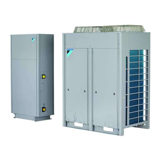
Split packaged air-cooled water chiller
Hide thumbs
Also See for SERHQ032BAW1:
- Installation and operation manual (60 pages) ,
- Installer and user reference manual (72 pages) ,
- Installation and operation manual (52 pages)
Table of Contents
Troubleshooting

Subscribe to Our Youtube Channel
Related Manuals for Daikin SERHQ032BAW1


Summary of Contents for Daikin SERHQ032BAW1
- Page 1 Installer and user reference guide Split packaged air-cooled water chiller SERHQ020BAW1 SERHQ032BAW1 SEHVX20BAW SEHVX32BAW Installer and user reference guide SEHVX40BAW English Split packaged air-cooled water chiller SEHVX64BAW...
-
Page 2: Table Of Contents
Table of contents 6 Installation Table of contents Overview: Installation ..............16 Opening the units ............... 17 6.2.1 About opening the units ..........17 6.2.2 To open the outdoor unit..........17 1 General safety precautions 6.2.3 To open the indoor unit ..........17 About the documentation ............ -
Page 3: General Safety Precautions
1 General safety precautions 7.2.7 Mode 1: Monitoring settings........36 16.3.6 Schedule timer ............. 65 7.2.8 Mode 2: Field settings..........37 16.3.7 Operating the optional demand PCB ......69 7.2.9 Field settings on the user interface ......38 16.3.8 Operating the optional external control adapter... 69 Using the leak detection function .......... -
Page 4: For The User
Make sure installation, testing and applied materials comply with applicable legislation (on top of the For the user instructions described in the Daikin documentation). ▪ If you are NOT sure how to operate the unit, contact your installer. CAUTION ▪ This appliance can be used by children aged from 8 years and... -
Page 5: Refrigerant
1 General safety precautions ▪ Make sure the area is well ventilated. Do NOT block any NOTICE ventilation openings. ▪ To avoid compressor breakdown, do NOT charge more ▪ Make sure the unit is level. than the specified amount of refrigerant. ▪... -
Page 6: Water
2 About the documentation WARNING NOTICE The use and installation of the application MUST comply Precautions when laying power wiring: with the safety and environmental precautions specified in the applicable legislation. 1.3.5 Water If applicable. See the installation manual or installer reference guide ▪... -
Page 7: Installer And User Reference Guide At A Glance
Daikin website (publicly accessible). Hand‑over to the user What to give and explain to the user ▪ The full set of latest technical data is available on the Daikin Maintenance and service How to maintain and service the units extranet (authentication required). -
Page 8: To Handle The Outdoor Unit
3 About the box 3.2.2 To handle the outdoor unit Indoor unit ▪ Lift the unit preferably with a crane and 2 belts of at least 8 m long 3.3.1 To unpack the indoor unit as shown in the figure below. Always use protectors to prevent belt damage and pay attention to the position of the unit's centre Remove the packaging material from the unit: of gravity. -
Page 9: About The Units And Options
4 About the units and options 3.3.3 To remove the accessories from the 4.2.1 Identification label: Outdoor unit indoor unit Location 1× 1× 1× 8× 2× 1×/2× 1× 1× 2× 2× 3× 2× Model identification Example: SE RH Q 020 BA W1 Code Explanation General safety precautions... -
Page 10: About The Indoor Unit
5 Preparation Leaving water condenser temperature (°C) 4.2.4 About the indoor unit Entering water condenser temperature (°C) Pull up area The SEHVX indoor units are intended for indoor installation and can Standard water operation range be used for air conditioning purposes or for supplying water for process cooling applications. -
Page 11: Preparing The Installation Site
5 Preparation ▪ In heavy snowfall areas, select an installation site where snow will Preparing the installation site not affect the operation of the unit. Seaside installation. Make sure the outdoor unit is NOT directly 5.2.1 Installation site requirements of the exposed to sea winds. -
Page 12: Installation Site Requirements Of The Indoor Unit
▪ Piping connection sizes Indoor unit Liquid Outdoor unit Liquid SEHVX20BAW Ø25.4 mm Ø12.7 mm 1× SERHQ020BAW1 Ø22.2 mm Ø9.52 mm SEHVX32BAW Ø25.4 mm Ø12.7 mm 1× SERHQ032BAW1 Ø28.6 mm Ø12.7 mm SEHVX40BAW Ø25.4 mm Ø12.7 mm 2× SERHQ020BAW1 Ø22.2 mm Ø9.52 mm SEHVX64BAW Ø25.4 mm Ø12.7 mm 2× SERHQ032BAW1 Ø28.6 mm Ø12.7 mm ▪... -
Page 13: About The Piping Length
5 Preparation ▪ Drainage – Low points. Provide drain taps at all low points of the Indoor unit G/G1 L/L1 system in order to allow complete drainage of the water circuit. SEHVX20BAW Ø28.6 mm Ø9.52 mm — — ▪ Non-brass metallic piping. When using non-brass metallic SEHVX32BAW Ø28.6 mm Ø12.7 mm —... -
Page 14: Formula To Calculate The Expansion Vessel Pre-Pressure
5 Preparation ▪ The maximum water piping temperature is 50°C according to INFORMATION safety device setting. The temperature step difference can be modified using ▪ Always use materials which are compatible with the water used in settings [A‑02] and [F‑00]. This has an impact on the the system and with the materials used in the unit. -
Page 15: Changing The Pre-Pressure Of The Expansion Vessel
5 Preparation When multiplying 64 l by the correction factor, we get 224 l, which will be the minimum water volume allowed in the installation if a temperature differential of 1 K is used. Now it is very important to check that for the height difference of the system, the volume in the system is less than the maximum allowed value at that pre-pressure (Pg). -
Page 16: About Electrical Compliance
Recommended fuses greater than or equal to the minimum S value at the interface SERHQ020BAW1 32 A point between the user's supply and the public system. SERHQ032BAW1 40 A ▪ EN/IEC 61000‑3‑12 European/International Technical Standard setting the limits for harmonic currents produced by... -
Page 17: Opening The Units
6 Installation 4× Opening the units 6.2.1 About opening the units At certain times, you have to open the unit. Example: ▪ When connecting the electrical wiring ▪ When maintaining or servicing the unit DANGER: RISK OF ELECTROCUTION Do NOT leave the unit unattended when the service cover is removed. -
Page 18: To Open The Electrical Component Box Of The Indoor Unit
6 Installation Allowed 6.2.5 To open the electrical component box of ▪ The height of the foundation must at least be 150 mm from the the indoor unit floor. In heavy snowfall areas, this height should be increased, depending on the installation place and condition. NOTICE ▪... -
Page 19: Precautions When Mounting The Indoor Unit
6 Installation 6.4.2 Precautions when mounting the indoor unit INFORMATION Also read the precautions and requirements in the following chapters: ▪ General safety precautions ▪ Preparation 6.4.3 To provide the installation structure Attach one L-shaped support to the left side of the top plate using 2 screws from the accessory bag Make sure the unit is installed level on a sufficiently strong base to Attach the other L-shaped support to the right side of the... -
Page 20: To Braze The Pipe End
6 Installation Service port 6.5.2 To braze the pipe end Stop valve cover Hexagon hole NOTICE Shaft Seal Precautions when connecting field piping. Add brazing ▪ Keep both stop valves open during operation. material as shown in the figure. ≤Ø25.4 >Ø25.4 ▪... -
Page 21: To Connect The Refrigerant Piping To The Outdoor Unit
6 Installation 6.5.4 To connect the refrigerant piping to the outdoor unit NOTICE All field piping must be installed by a licensed refrigeration technician and must comply with the relevant local and national regulations. Seal the piping and wiring intake holes using sealing material (field supply), otherwise the capacity of the unit will drop and small animals may enter the machine. -
Page 22: To Connect The Refrigerant Piping To The Indoor Unit
6 Installation NOTICE Precautions when making knockout holes: ▪ Avoid damaging the casing. ▪ After making the knockout holes, we recommend you remove the burrs and paint the edges and areas around the edges using repair paint to prevent rusting. ▪... -
Page 23: Checking The Refrigerant Piping
6 Installation 6.6.2 Precautions when checking the refrigerant piping INFORMATION Also read the precautions and requirements in the following chapters: ▪ General safety precautions ▪ Preparation NOTICE Use a 2-stage vacuum pump with a non-return valve that can evacuate to a gauge pressure of − 1 00.7 kPa (−... -
Page 24: To Insulate The Refrigerant Piping
6 Installation 2 Check that, with the vacuum pump turned off, the target To speed up the refrigerant charging process, it is in case of larger vacuum is maintained for at least 1 hour. systems recommended to first pre-charge a portion of refrigerant through the liquid line before proceeding with the actual automatic or 3 Should you fail to reach the target vacuum within 2 hours or manual charging. -
Page 25: To Determine The Additional Refrigerant Amount
1, 2 operating the outdoor unit by means of the automatic refrigerant Example charge operation mode. SEHVX64BAW + 2× SERHQ032BAW1 Depending on the ambient limitation conditions (see above), the unit R=(L1+L2) ×0.12 will automatically decide which operation mode will be used to fulfill Ø12.7... - Page 26 6 Installation Out of outdoor temperature range * = The state of this LED is not important. Out of indoor temperature NOTICE range When a malfunction occurs, check the user interface Within range display and refer to "6.7.5 Error codes when charging 6 Press BS1 once to complete charging.
-
Page 27: Error Codes When Charging Refrigerant
6 Installation 6 Record the amount that was added on the additional refrigerant Waiting for stable heating charge label provided with the unit and attach it on the back conditions (next ±15 minutes side of the front panel. (depending on the system)) 7 Perform the test procedure described in "8.6.2 ... -
Page 28: To Input The Additional Refrigerant Charge Weight
6 Installation However, the refrigerant leak detection function cannot be used Value number Weight (kg) LEDs before completing the refrigerant charging operation and the 5≤x<10 judgement of the initial amount of refrigerant by performing the test 10≤x<15 operation again. 15≤x<20 Overcharging judgement procedure 20≤x<25 1 Close all front panels except the electrical component box front... -
Page 29: Connecting The Water Piping
6 Installation ▪ For correct operation of the system, a regulating valve must be NOTICE installed in the water system. The regulating valve is to be used to In Europe, the greenhouse gas emissions of the total regulate the water flow in the system (field supply). refrigerant charge in the system (expressed as tonnes CO equivalent) is used to determine the maintenance intervals. -
Page 30: Precautions When Connecting Electrical Wiring
6 Installation Typical workflow NOTICE Connecting the electrical wiring typically consists of the following If the power supply has a missing or wrong N-phase, stages: equipment will break down. Making sure the power supply system complies with the NOTICE electrical specifications of the units. Connecting the electrical wiring to the outdoor unit. -
Page 31: Field Wiring: Overview
6 Installation ▪ Maximum number of independent interconnectable systems: 10. NOTICE For the above wiring, always use vinyl cords with 0.75 to 1.25 mm Improper connections or installation may result in fire. sheath or cables (2-core wires). (3-core wire cables are allowable for the cooler/heater changeover user interface only.) WARNING ▪... -
Page 32: To Connect The Power Supply Of The Outdoor Unit
6 Installation System example Field power supply Main switch Earth leakage breaker Outdoor unit Indoor unit User interface Power supply wiring (sheathed cable) (230 V) SERHQ032 Transmission wiring (sheathed cable) (16 V) 6.9.6 To connect the power supply of the outdoor unit Power supply (400 V, 3N~ 50 Hz) Fuse... -
Page 33: To Connect The Power Supply And Transmission Cables
6 Installation Tightening torque for the terminal screws The outdoor unit PC board (A1P) is factory set to "Sequential start available". Screw size Tightening torque (N•m) M8 (Power terminal block) 5.5~7.3 6.9.7 To connect the power supply and M8 (earth) transmission cables M3 (Inter-unit wiring terminal 0.8~0.97... -
Page 34: To Install The User Interface
6 Installation ▪ When passing electrical wiring through the knockout holes. prevent damage to the wires by wrapping the wiring with protective tape, putting the wires through field supplied protective wire conduits at that location, or install suitable field supplied wire nipples or rubber bushings into the knockout holes. -
Page 35: Configuration
7 Configuration To continue the configuration of the system, it is required to give Configuration some input to the PCB of the unit. This chapter will describe how manual input is possible by operating the pushbuttons/DIP switches on the PCB and reading the feedback from the LEDs. Overview: Configuration INFORMATION This chapter describes what you have to do and know to configure... -
Page 36: To Access Mode 1 Or 2
7 Configuration 7.2.5 To use mode 1 Mode 1 is used to monitor the status of the unit. What Accessing monitoring Once mode 1 is selected (push BS1 mode 1 one time), you can select the wanted setting. It is done by pushing BS2. To quit and return to the Press BS1. -
Page 37: Mode 2: Field Settings
7 Configuration Value / Description Value / Description Shows the status of low noise operation. Shows the status of power consumption limitation operation. Unit is currently not operating under low noise Unit is currently not operating under power restrictions. consumption limitations. Unit is currently operating under low noise Unit is currently operating under power restrictions. -
Page 38: Field Settings On The User Interface
7 Configuration Setting Value Description (= binary) Deactivated Refrigerant recovery/vacuuming mode. (default) Activated This is a field setting of the outdoor module. In case of SEHVX40+64BAW, perform the setting on both outdoor modules. In order to achieve a free pathway to reclaim refrigerant out of the system or to remove residual substances or to vacuum the system, it is necessary to apply a setting which will open the required valves in the refrigerant circuit so the reclaim of refrigerant or... - Page 39 7 Configuration After entering the field setting, the selected permission level must be enabled by simultaneously pressing , immediately 22°C 22°C followed by simultaneously pressing . Keep all 4 buttons 21°C 21°C 45°C 45°C pressed for at least 5 seconds. Note that no indication on the user 44°C 44°C 19°C...
- Page 40 7 Configuration 22°C 22°C 21°C 21°C 21°C 45°C 45°C 44°C 44°C 19°C 19°C 19°C 19°C 19°C 19°C 18°C 42°C 42°C 42°C 42°C 42°C 42°C [2-01] [2-02] Normal room temperature setpoint 0:30 6:30 9:00 16:00 Room setback temperature [5-03] Time Temperature Setback configured for leaving water temperature control 18°C 18°C...
- Page 41 7 Configuration [6‑01] Description External room thermostat input 1 = heating operation ON (1)/OFF (0). Lo_Ti External room thermostat input 2 = cooling + 05 operation ON (1)/OFF (0). Shift value Hi_Ti External room thermostat input 1 = operation – 05 ON (1)/OFF (0).
-
Page 42: Using The Leak Detection Function
7 Configuration [9‑00] Leaving water temperature compensation value for [E‑03] heating operation This setting is not applicable. [9‑01] Leaving water thermistor auto corrective function [E‑04] Pump only operation (air purge function) This function will take into account the outdoor ambient conditions When installing and commissioning the unit it is very important to and correct the measured value which will be used for the logic. -
Page 43: Switching Between Cooling And Heating
8 Commissioning If the indoor temperature is lower than 15°C due to leak INFORMATION detection operation and the outdoor temperature is lower Thermostat input priority over leaving water than 20°C, the heating operation will start to maintain basic temperature setpoint. comfort heating level. -
Page 44: Checklist Before Commissioning The Outdoor Unit
8 Commissioning Power supply wiring and transmission wiring Checklist before commissioning the outdoor unit Use a designated power supply and transmission wiring and make sure that it has been carried out according to After the installation of the unit, first check the following items. Once the instructions described in this manual, according to the all below checks are fulfilled, the unit MUST be closed, ONLY then wiring diagrams and according to local and national... -
Page 45: Final Check
8 Commissioning Pump rotation direction Final check If the 3-phase power input to the indoor unit is not Before switching on the unit, read the following recommendations: correctly wired (X1M), the pump may rotate in the wrong direction. When this happens, the pump may slowly ▪... -
Page 46: Refrigerant Added Using Manual Charging (Heating Mode, Pre-Charging)
8 Commissioning Test run procedure ▪ Piping length 1 Close all front panels except the one on the side of the This checking operation takes ±30 minutes to complete. electrical component box. Check operation procedure 2 Turn on the power to the outdoor unit and all connected indoor 1 Close the electrical component box lid and all front panels units. -
Page 47: To Complete The Model Fill-In
9 Maintenance and service WARNING To complete the model fill-in ▪ Before carrying out any maintenance or repair activity, Complete the following fill-in for each unit: ALWAYS switch off the circuit breaker on the supply panel, remove the fuses or open the protection devices Place of of the unit. -
Page 48: Checklist For Yearly Maintenance Of The Indoor Unit
10 Troubleshooting 1 With the unit at a standstill and setting mode 2 active, set the ▪ Water pressure relief valve required function B (refrigerant recovery operation/vacuuming ▪ Electrical component box operation) to ON (ON). ▪ Water pressure Result: The indoor unit and the outdoor unit expansion valves open completely and some solenoid valves are turned on. -
Page 49: Error Codes Of The Outdoor Unit
11 Disposal Main code Cause Solution Returning water thermistor error (R12T/R22T) ▪ Check wiring connections. ▪ Contact your local dealer. Heating leaving water thermistor error (R11T/R12T) ▪ Check wiring connections. ▪ Contact your local dealer. User interface thermostat thermistor error Contact your local dealer. -
Page 50: 12 Technical Data
12 Technical data Technical data A subset of the latest technical data is available on the regional Daikin website (publicly accessible). The full set of latest technical data is available on the Daikin extranet (authentication required). 12.1 Overview: Technical data... - Page 51 12 Technical data INFORMATION Further specifications can be found in the technical engineering data. SERHQ020~032BAW1 + SEHVX20~64BAW Installer and user reference guide Split packaged air-cooled water chiller 4P508020-1A – 2018.01...
-
Page 52: Piping Diagram: Outdoor Unit
12 Technical data 12.4 Piping diagram: Outdoor unit 20 kW 32 kW SENPH SENPH STD1 STD2 SENPL SENPL Check valve Electronic expansion valve Pressure regulating valve Filter Heat exchanger Accumulator 4-way valve High pressure sensor High pressure switch Solenoid valve Compressor Capillary tube Oil separator... -
Page 53: Piping Diagram: Indoor Unit
12 Technical data 12.5 Piping diagram: Indoor unit R11T R14T R12T R13T Air purge valve Temperature sensors (R11T, R12T, R13T, R14T) Expansion vessel (12 l) Shut-off valve (field installed) Water inlet connection Water outlet connection Drain port Water filter Pressure gauge Flow switch Pump Safety valve... -
Page 54: Wiring Diagram: Outdoor Unit
12 Technical data 12.6 Wiring diagram: Outdoor unit Refer to the wiring diagram sticker on the outdoor unit. The Thermistor (suction) abbreviations used are listed below: Thermistor (coil-deicer) INFORMATION Thermistor (coil-outlet) The wiring diagram on the outdoor unit is only for the Thermistor (liquid-pipe receiver) outdoor unit. -
Page 55: Wiring Diagram: Indoor Unit
12 Technical data 12.7 Wiring diagram: Indoor unit Refer to the wiring diagram sticker on the indoor unit. The Operation ON input (field supply) abbreviations used are listed below: Operation OFF input (field supply) L1,L2,L3 Live SS1 (A1P, A5P) Selector switch (emergency) Neutral SS1 (A2P) Selector switch (master/slave) -
Page 56: Technical Specifications: Outdoor Unit
12 Technical data 12.8 Technical specifications: Outdoor unit INFORMATION technical electrical details, technical engineering data. Installer and user reference guide SERHQ020~032BAW1 + SEHVX20~64BAW Split packaged air-cooled water chiller 4P508020-1A – 2018.01... -
Page 57: Field Settings On The User Interface - Overview
12 Technical data 12.9 Field settings on the user interface – overview 1st code 2nd Setting name Date Value Date Value Default Range Step Unit code value User interface setup User permission level — Room temperature compensation value –5~5 °C Not applicable. - Page 58 12 Technical data 1st code 2nd Setting name Date Value Date Value Default Range Step Unit code value Settings are not applicable Not applicable. Do not change the default value. — — — — — Not applicable. Do not change the default value. —...
-
Page 59: 12.10 Field Settings On The Outdoor Unit
12 Technical data 12.10 Field settings on the outdoor unit Technical specifications Setting Setting contents Contents Factory Selected Date setting condition Low noise/demand setting via external control adapter High static pressure setting Automatic night-time low noise setting Level 1 (outdoor fan with step 6 or lower) Level 2 (outdoor fan with step 5 or lower) -
Page 60: 12.11 Esp Curve: Indoor Unit
13 About the system 12.11 ESP curve: Indoor unit External static pressure (kPa) Water flow (l/min) SEHVX20BAW SEHVX32BAW SEHVX40BAW SEHVX64BAW For the user 13.1 System layout About the system NOTICE Do not use the system for other purposes. In order to avoid any quality deterioration, do not use the unit for cooling precision instruments or works of art. -
Page 61: 14 User Interface
14 User interface WARNING User interface Avoid placing the controller in a place where it can be CAUTION splashed with water. Water entering the machine may cause an electric leak or may damage the internal ▪ NEVER touch the internal parts of the controller. electronic parts. -
Page 62: 16 Operation
Only use a fire. accessories, optional equipment and spare parts made or approved by Daikin. CAUTION This operation manual is for the following systems with standard It is not good for your health to expose your body to the air control. -
Page 63: Operating The System
16 Operation Select mode (heating h or cooling c) Push bi or bj Display: - starts to blink Display: "n" Set desired room temperature The remote controller room (e.g. 22°C) thermostat function is not installed Push ébi or ébj You have "room temperature You have "leaving water temperature based"... -
Page 64: About Operating The System
16 Operation 16.3.2 About operating the system INFORMATION Setback operation and weather dependent setpoint are not If the main power supply is turned off during operation, operation will available in the cooling mode. restart automatically after the power turns back on again. 16.3.4 Space heating operation 16.3.3... -
Page 65: Other Operation Modes
16 Operation 2 Press again to deactivate quiet mode operation. To switch space heating on/off using leaving water temperature control Result: disappears from the display. The actual temperatures can be displayed on the remote controller. In this mode, heating will be activated as required by the water temperature setpoint. - Page 66 16 Operation Space heating based on ON/OFF instruction Space heating based on temperature setpoint During operation When the schedule timer switches space During operation During schedule timer operation the operation heating OFF, the controller will be switched off LED is lit continuously. (operation LED will stop working).
- Page 67 16 Operation 10 Select using to switch cooling and the remote INFORMATION controller off. Space cooling based on temperature setpoint is enabled 11 Repeat this procedure to program the other actions. by default, so only temperature shifts are possible (no ON/ OFF instruction).
- Page 68 16 Operation INFORMATION To program quiet mode Press to return to previous steps in the programming procedure without saving modified settings. 1 Press to enter the programming/consulting mode. 2 Select the operation mode you would like to program using Result: The actual mode is blinking. 3 Press to confirm the selected mode.
-
Page 69: Operating The Optional Demand Pcb
17 Maintenance and service 2 Select the operation mode you would like to consult using 3 Press simultaneously for 5 seconds to delete the selected mode. Result: The actual mode is blinking. To delete a day of the week 3 Press to confirm the selected mode. -
Page 70: About The Refrigerant
18 Troubleshooting WARNING 17.2.3 Recommended maintenance and inspection cycles Never replace a fuse with a fuse of a wrong ampere ratings or other wires when a fuse blows out. Use of wire or Be aware that the mentioned maintenance and replacement cycles copper wire may cause the unit to break down or cause a do not relate to the warranty period of the components. -
Page 71: Error Codes: Overview
18 Troubleshooting Malfunction Measure Malfunction Measure If a safety device such as a fuse, a Turn OFF the main power The system operates ▪ Check if air inlet or outlet of outdoor or breaker or an earth leakage breaker switch. but cooling or heating indoor unit is not blocked by obstacles. - Page 72 19 Relocation Field supply Main code Contents Equipment NOT made by Daikin that can be combined with Type connection problem (indoor unit) product according instructions Auto address malfunction (inconsistency) (indoor unit) accompanying documentation. Relocation Contact your dealer for removing and reinstalling the total unit.
- Page 76 4P508020-1A 2018.01...
Need help?
Do you have a question about the SERHQ032BAW1 and is the answer not in the manual?
Questions and answers