
Summary of Contents for Nice Apollo CBOX1K
- Page 1 Nice Apollo Control CBOX1K Vehicular Gate Operator Control Revision 1.0.0.0_6-2014...
-
Page 3: Table Of Contents
TABLE OF CONTENTS CAUTIONS AND NOTES 10 - 35001K & 36001K INSTALLATION EXTREMELY IMPORTANT 10.1 - Parts indentification 10.2 - Post installation ETL DEFINITIONS COMPLIANT TO UL325 10.3 - Chassis mounting 1 - OVERVIEW 10.4 - Control arm assembly 1.1 - Main control board 10.5 - Gate bracket mounting 10.6 - Chassis wiring 1.2 - Main control board specifics... -
Page 4: Cautions And Notes
CAUTIONS AND NOTES 1.1 - 1050 control board The 1050 main control board is housed in a protective plastic enclosure This instruction manual is intended to aid the installer in the overall process that includes a 2-line LCD and with 5 dedicated buttons and 3 buttons for of correct installation at the desired location. -
Page 5: Gate Latches
2.2 - Gate latches • Follow the recommended maintenance schedule of one inspection per every 180 days of use. In association with this gate controller and these operators, at no time should • Do not allow children to play in the area of the operator or to play with any manual gate latches or locks be used. -
Page 6: Gate System Safety Devices
3.3 - Gate system safety devices • A minimum of two (2) WARNING SIGNS shall be installed, one on each side of the gate where easily visible. Automatic gate operators are designed to move a heavy steel gate. Great • Test all features for proper functions before placing the automatic vehicular amounts of force are sometimes used to move these heavy systems. - Page 7 4.3.16 Protrusions shall not be permitted on any gate, refer to ASTM F2200 4.3.37 Any controls used to reset the device after obstruction/entrapment for exceptions, if any. protection incidents should be located within view of the gate and should have safety features that prevent unauthorized use. 4.3.17 Gates shall not be designed, constructed and installed in such a man- ner that gravity will cause or initiate movement in any direction whether 4.3.38 Never allow anyone to ride, hang on or otherwise touch the gate.
-
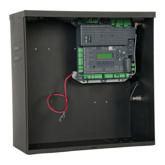
Page 8: Circuit Board Layout
5 - CIRCUIT BOARD LAYOUT Power Input Motor Output Connections Connections Accessory Output Connections BlueBus Connection Master / Slave Connection Earth Ground Accessory Input Connections 6 - INCOMING POWER WIRING Power input connections should be wired as follows: Solar panel Connect wires to the solar panel terminal block. -
Page 9: Control Box Mounting
The CBOX1K control box is used for many different model operators. The following pages show installation guides for these models. Refer to the correct model operator section for instructions on how to install and wire the actuators and motors to the control board and proper setup of the limit swiches. -
Page 10: Nt-T51K & Nt-T71K Installation
8 - NT-T51K & NT-T71K INSTALLATION 8.1 - PARTS IDENTIFICATION T5 Actuator #NT-TO5012 T7 Actuator #NT-TO7012 Control Box #11111B Operator T5ETL-1K T7ETL-1K... -
Page 11: Pivot Arm Installation
8.2 - PIVOT ARM INSTALLATION 4 ½” 38” Pull to Open installation T5 Actuator Dimensions 5” ” T7 Actuator Dimensions IMPORTANT - Never weld parts to the gate or posts when the operator circuit board is powered. Doing so may damage the board beyond repair. -
Page 12: T5 Pivot Arm Bracket Location Graph
8.3 - T5 ACTUATOR PIVOT BRACKET LOCATION GRAPH T5 Actuator Pivot Bracket Location Graph 90° to 100° 13-3/8 10-5/8 12-5/8 9-3/4 12-3/16 100° to 110° 11-13/16 11-7/16 8-1/4 10-5/8 Recommended 10-1/4 installation line 9-13/16 7-1/2 9-7/16 110° to 120° 6-3/4 9-1/16 8-11/16 8-1/4... -
Page 13: T7 Pivot Arm Bracket Location Graph
8.4 - T7 ACTUATOR PIVOT BRACKET LOCATION GRAPH T7 Actuator Pivot Bracket Location Graph up to 90° 11-13/16 11-7/16 8-1/4 Recommended installation line 10-5/8 7-1/2 10-1/4 90° to 95° 9-13/16 6-3/4 9-7/16 95° to 100° 9-1/16 8-11/16 8-1/4 7-7/8 5-1/8 7-1/2 7-1/16 4-1/2... -
Page 14: Gate Bracket Mounting
8.5 - GATE BRACKET MOUNTING Attach the gate attachment bracket to the gate based on the position and dimension. The T5/T7 gate operator must be fastened to the gate in a completely level position. Ensure that the gate attachment bracket is located at a “hard point” on the gate suitable for opening or closing the gate. -
Page 15: Actuator Wiring
8.7 - ACTUATOR WIRING Connect the T5/T7 cable to the 5-pin connector as shown below for push to open installations. Tighten the wire terminals to complete the wiring connection to the T5/T7. Re-attach the cover and secure with the Green T5, T7 provided Phillips-head screws. -
Page 16: Limit Switch Adjustment
Test motor direction by pressing OPEN. If the gate instead 8.9 - LIMIT SWITCH ADJUSTMENT CLOSES swap the RED and BLACK motor leads. The control board is already in the “LEARNING MODE” Using the OPEN button on the front of the Control board, when shipped. -
Page 17: 15501K & 16501K Installation
9 - 15501K & 16501K INSTALLATION 9.1 - PARTS IDENTIFICATION 816 - Actuator with 8’ harness 816X - Actuator with 38’ harness Control Box #11111B (Supplied with 16501K) Gate attach bracket #10025215 Pivot Arm #1116 Bolt kit (2 with 16501K) (2 with 16501K) (2 with 16501K) -
Page 18: Pull To Open Installation
9.2 - PULL TO OPEN INSTALLATION IMPORTANT - Never weld parts to the gate or posts when the operator circuit board is powered. Doing so may damage the board beyond repair. PIVOT ARM INSTALLATION - Location of Pivot Point The following instructions provide up to 105° of swing. Measurements are taken from the center of pivot of the gate hinge. -
Page 19: Push To Open Installation
9.3 - PUSH TO OPEN INSTALLATION PIVOT ARM INSTALLATION - Location of Pivot Point Measurements are taken from the center of pivot of the gate hinge. The pivot arm needs to be securely mounted to the hinge post or equivalent mounting surface. It is recommended to weld the pivot arm to a metal post. -
Page 20: Actuator Wiring
9.5 - ACTUATOR WIRING 816 ACTUATOR WIRING (STANDARD) 816 ACTUATOR WIRING (PUSH TO OPEN) 816 limit switch and smart sensor wiring 816 limit switch and smart sensor wiring Connect the Apollo 816 actuator cable to the 5-pin connector Connect the Apollo 816 actuator cable to the 5-pin connector as shown below. -
Page 21: Limit & Motor Connection To The Board
9.7 - LIMIT AND MOTOR CONNECTION TO THE BOARD Install the 5 and 3-pin connector for motor 1 into the connection labeled “Motor 1” on the controller as shown. For a dual gate installation install the 5 and 3-pin and connector for motor 2 into the connection labeled “Motor 2”. -
Page 22: Setting Limit Switches
9.9 - SETTING THE LIMIT SWITCHES The control board is already in the “LEARNING MODE” when shipped. If the board is not in “LEARN MODE” press FUNCTION then select LEARN then SWING then MOTOR 1 LED - GREEN MOTOR 2 LED - GREEN LIGHT, AVERAGE OR HEAVY, then press ENTER. -
Page 23: 35001K & 36001K Installation
10 - 35001K & 36001K INSTALLATION 10.1 - PARTS IDENTIFICATION Chassis #CHBOX350 Control Box #CBOX1K Arm Assembly #ABOX350... -
Page 24: Post Installation
10.2 - POST INSTALLATION IMPORTANT - Never weld parts to the gate or posts when the operator circuit board is powered. Doing so may damage the board beyond repair. Post location guide Determine the angle that the gate will open to (A). Select the coordinates (B&C) as shown on the chart below. Distances are from the hinges square to the center of the mounting post. -
Page 25: Chassis Mounting
Post height The 3500 operator is designed for installation using a 4”x4” square post with 1/4” wall thickness (not supplied). 1. Determine the height on the gate where the arm will 2” attach to. 2. The top of the post should be 2” above the centerline Horizontal of the location where the gate attach bracket will be center line of... -
Page 26: Control Arm Assembly
10.4 - CONTROL ARM ASSEMBLY Install the primary arm collar to the main drive shaft using the 1/4” key stock and set screws. The collar should be installed on the shaft as far up as possible. Tighten set screws in place Attach the primary arm to the collar, the two ears on the primary arm should point toward the direction the gate will close. -
Page 27: Gate Bracket Mounting
10.5 - GATE BRACKET MOUNTING Push the arm assembly up against the gate in the closed position. Make sure that the primary arm is locked into the stop tab on the secondary arm as shown below. Tack weld or clamp the gate attach bracket to the gate. Note: Permanent welds or bolt attachment should be completed once limits are set. -
Page 28: Limit & Motor Wiring
10.7 - LIMIT AND MOTOR WIRING 3500/3600 WIRING (LEFT HINGED GATE) 3500/3600 WIRING (RIGHT HINGED GATE) Limit switch wiring Limit switch wiring Connect the 3500 cable to the 5-pin connector as shown Connect the 3500 cable to the 5-pin connector as shown below. -
Page 29: Setting Limit Switches
10.9 - SETTING THE LIMIT SWITCHES Open Loosen set screws on both limit cams to the point where Limit each cam can be turned by hand but still hold its place on the shaft. Close Limit The control board is already in the “LEARNING MODE” when shipped. -
Page 30: Learning Mode
11 - LEARNING MODE Apollo has taken great care to simplify the installation, operation and safety of this device and to ensure longevity and reliability of the unit over time. The learning procedure consists of the following steps shown below: UP SELECTION ARROW OK BUTTON DOWN SELECTION ARROW... -
Page 31: Accessory Inputs And Outputs
GATE OPERATOR ACCESSORY INPUTS: 12 - ACCESSORY INPUTS AND OUTPUTS Auxiliary Inputs 1 (16) and 2 (18): These digital inputs may be connected to the digital outputs of accessories and programmed to activate or control 12.1 - Outputs the gate operator in a number of different modes. Shorting the pins through a dry contact activates the programmed settings for these inputs. -
Page 32: Communication Buses
12.3 - Communication buses On the Slave operator, select Function -> Adv. Settings -> Remote Mst. Slv. Then select On -> Slave. The red LED associated with the Master/Slave connector will illuminate. The Master/Slave pair is now configured. The Slave gate operator will perform identical open/close/stop functions in tandem with the Master gate operator. -
Page 33: 120Vac Power Wiring
Note: Double the amount of solar wattage for dual gate operators • All wiring connections MUST be made by a qualified individual Nice Apollo operators with the 1050 board that are used in solar applications • Run individual circuits in separate U.L. listed conduits. Do not combine need to be put into “Standby”... -
Page 34: Optional Inputs
15 - OPTIONAL INPUTS 15.1 - Fire dept. connection 32 FIRE 33 GND Dry contact input for a fire department control switch. Normally Open (NO) contact must be shorted to ground through a switch to open the gate. The FAIL SAFE connector which is shorted at the factory with a jumper C L O (Normally Closed NC), may be wired in parallel with the Fire input to release the... -
Page 35: Radio Receiver Connection (Third Party)
16 - INSPECTION AND OPERATION 15.5 - Radio receiver connection (third party) Proper inspection of all equipment is required to ensure continuous functionality, safety and to ensure reliable operation in all weather conditions. 38 12V Inspect electrical assemblies and wiring installations for damage, general 39 OPEN condition, and proper functioning to ensure the continued satisfactory 40 CLOSE... -
Page 36: General Layout And Safety Access
17 - GENERAL LAYOUT AND SAFETY ACCESS Entrapment Protection Inputs - Typical Installation Diagram Utilizing Loop Sensors and Photocells Loop (Safety) Outside Gate 4’ Min. from closed gate 4’ Min. from closed gate Loop (Shadow) Photo 2 Photo 2 4’ Min. from open gate Loop (Safety) Loop (Exit) Figure - LAYOUT FOR IN-GROUND LOOPS... -
Page 37: Accessories And Sensors
18 - ACCESSORIES AND SENSORS EXTERNAL ENTRAPMENT PROTECTION Non-contact and contact sensors must be installed individually or in combination with each other to provide external entrapment protection. Care should be exercised to reduce the risk of nuisance tripping, such as when a vehicle trips the sensor while the gate is still moving, and one or more non- contact sensors shall be located where the risk of entrapment or obstruction exists, such as the perimeter reachable by a moving gate or barrier. -
Page 38: Board Nomenclature
19 - BOARD NOMENCLATURE Incoming 30 LCD screen Amp fuse Spare fuses Open the gate Stop gate movement Reset Hard Shut down button Close the gate Selection up OK or Enter Selection down Force select Speed select Delay select Function select Display select Figure - GENERAL BOARD OVERVIEW THE PROGRAMMING BUTTONS INDICATED IN THE ABOVE REFERENCE SHOULD BE USED ONLY AFTER UNDERSTANDING THE... -
Page 39: Programming Buttons
• Slow Down – Close: Sets the % of gate opening when the gate begins 20 - PROGRAMMING BUTTONS deceleration to the fully close position. • Partial: Sets the point in the % of gate opening when the gate begins when given a PARTIAL command. -
Page 40: Display
be assigned to any combination of days of the week (Monday through • Set Anti-tailgate (Closes gate immediately after vehicle has cleared safety Sunday). Events that are already programmed into the system may be sensors) suspended temporarily, or removed permanently from memory. The following •... -
Page 41: Emergency Vehicle Access
21 - EMERGENCY VEHICLE ACCESS 22 - GLOSSARY 21.1 The automatic vehicular gate system must be designed to allow LOCK- Ceases all operator function except HIGH PRIORITY inputs. access to emergency vehicles under different operating conditions. COMMERCIAL / GENERAL ACCESS VEHICULAR GATE OPERATOR- 21.2 During normal powered operation, emergency vehicles access the CLASS II - A vehicular gate operator (or system) intended for use in a gate by use of the emergency vehicle access device installed on your... -
Page 42: Maintenance Schedule
23 - MAINTENANCE SCHEDULE Table 2 COMPLETE BASIC Alarm Active the primary (inherent) reverse system by blocking the gate with a solid object. The gate should reverse momentarily then stop. Restart the gate and block again with a solid object. The ● ... -
Page 45: Warranty
27 - WARRANTY Nice Group USA Limited Warranty – 2 (TWO) YEARS Nice Group USA (“Manufacturer”) warrants this product shall be free from defects in materials and workmanship for a period of 2 years from the manufacture date. These warranties are in lieu of all other warranties expressed or implied and shall be considered void if the product is damaged due to, but not limited to, improper installation, improper use, terrorism or acts of God. -
Page 46: Installation Checklist
28 - INSTALLATION CHECKLIST Left box is for installer check off and the right box is for customer check off. ❑ ❑ 1. The gate has been checked to make sure it is level and moves freely in both directions. ❑ ❑ 2. Potential pinch areas have been guarded so as to be inaccessible OR have contact and/or non-contact obstruction sensing devices installed. - Page 48 Contact us Nice Group USA Inc. 12625 Wetmore Road Suite 218 San Antonio, TX 78247 Ph. +1.210.545.2900 Fax +1.210.545.2915 www.niceapollo.com www.facebook.com/NiceApollo...
Need help?
Do you have a question about the CBOX1K and is the answer not in the manual?
Questions and answers