Table of Contents
Advertisement
Quick Links
Advertisement
Table of Contents

Subscribe to Our Youtube Channel
Related Manuals for RS PRO RSSA3000X


Summary of Contents for RS PRO RSSA3000X
- Page 1 Quick Guide RSSA3000X Spectrum Analyzer...
-
Page 3: General Safety Summary
Electrostatic Prevention General Safety Summary Operate the instrument in an electrostatic discharge protective area environment to avoid damages induced by static discharge. Always Carefully read the following safety precautions to avoid any personal ground both the internal and external conductors of the cable to release injury or damage to the instrument and any products connected to it. - Page 4 General Safety Summary Safety Terms and Symbols Terms on the product. These terms may appear on the product: DANGER Indicates direct injuries or hazards that may happen. WARNING indicates potential injuries or hazards that may happen. CAUTION Indicates potential damages to the instrument or other property that may happen. Symbols on the product.
-
Page 5: General Care And Cleaning
General Care and Cleaning Care Do not store or leave the instrument in direct sunshine for extended periods of time. Notice: To avoid damages to the instrument, please do not leave it in fog, liquid, or solvent. Clean Please perform the following steps to clean the instrument regularly according to its operating conditions. 1. -
Page 6: General Inspection
General Inspection 1.Inspect the shipping container Keep the damaged shipping container or cushioning material until the contents of the shipment have been completely checked and the instrument has passed both electrical and mechanical tests. 2. Inspect the instrument If the instrument is found to be damaged, defective or fails in electrical or mechanical tests, please contact your sales representative. 3. -
Page 7: Appearance And Dimension
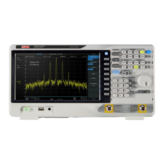
Appearance and Dimension Figure 1 Front View Figure 2 Top View... -
Page 8: Adjust The Supporting Legs
Adjust the Supporting Legs Adjust the supporting legs properly to use them as stands to tilt the Spectrum Analyzer upwards for stable placement as well as easier operation and observation of the instrument. Before adjusting After adjusting... -
Page 9: Connect To Ac Power Supply
Connect to AC Power Supply The Spectrum Analyzer accept 100-240V, 50/60/440Hz AC power supply. Please use the power cord provided as accessories to connect the instrument to the power source as shown in the figure below. -
Page 10: General Description
General Description This model of spectrum analyzer has a frequency range from 9 kHz up to 2.1 GHz/3.2 GHz. It is lightweight, small and precise, offering a user friendly interface, clear display with plenty of RF measurement functions. The product can be used for research and development, education, production, maintenance and other relevant applications. - Page 11 Details of the Various Functions: Frequency: Sets the Center Freq\Start Freq\Stop Freq\Freq Step Span: Sets the Span\Full Span\Zero Span\Zoom In\Zoom Out\Last Span Amplitude: Used to Set the REF Level\Attenuator\Preamp\Amplitude Auto Tune: Automatically sets the optimal parameters according to the characteristics of the signal BW: Used to adjust the RBW,VBW,VBW/RBW Rate, Average Type (Logpower\Power\Voltage) Trace: Selects Trace\Trace setup\Trace math Sweep: Selects the Sweep time\Sweep Rule\Sweep Mode...
- Page 12 Marker→: Sets all types of Markers to Freq Marker Fn: Selects the Noise Marker\N dB BW\Freq Counter\Read out of Freq Peak: Searches for the Peak Signal and Counts the Peak Frequency Meas: Selects the Channel Power\ACPR\Occupied BW\T-Power Meas Setup: Used to Choose the Parameters Details of Channel Power\ACPR\Occupied BW\T-Power System: Selects the Language\Power on/Preset\Interface\Calibration\system information\Data&Time\Self Test Mode: Selects the Spec Analyzer\EMI\Reflection Meas Display: Used to Adjust the Grid Brightness\Display Line...
- Page 13 The Rear Panel 1、Handle 2、USB Device 3、LANInterface 4、10MHz REFInput 5、10MHz REF Output 6、TriggerIn 7、SafetyLockHole 8、AC PowerSocket...
-
Page 14: Operation Notices
Operation Notices 1. RF INPUT WARNING To avoid damage to the instrument, make certain that the input signal to the RF input port does not contain more than 50 Volts DC. The AC (radio frequency) input signal component should not exceed a maximum continuous power level of +30dBm. 2. - Page 15 User Graphical Interface 1、3、4:Parameters 5、Active parameter setting area 6、Display area 2、Menu setting area...
-
Page 16: More Product Information
More Product Information You can obtain the instrument information including model, serial number as well as hardware and software version numbers through System ->Information. For more information of this product, please refer to the following manuals (provided in the “CD” in the accessories): Spectrum Analyzer User Manual: provides detailed introductions of the functions of this product;...
Need help?
Do you have a question about the RSSA3000X and is the answer not in the manual?
Questions and answers