Table of Contents
Advertisement
Advertisement
Table of Contents

Related Manuals for Furuno DFF1


Summary of Contents for Furuno DFF1
- Page 1 NETWORK SOUNDER DFF1...
- Page 2 • Store this manual in a convenient place for future reference. • FURUNO will assume no responsibility for the damage caused by improper use or modification of the equipment (including software) by an unauthorized agent or a third party.
- Page 3 Use of a wrong fuse can damage the equipment and may cause fire. A warning label is attached to the equipment. Do not remove these labels. If a label is missing or illegible, contact a FURUNO agent or dealer about replacement. WARNING To avoid electrical shock, do not remove cover.
- Page 4 Safety instructions for the installer WARNING Do not open the equipment. Only qualified personnel should work inside the equipment. Turn off the power before beginning the installation. Fire or electrical shock can result if the power is left on. Confirm that is no water leakage at the transducer and temperature sensor.
-
Page 5: Table Of Contents
TABLE OF CONTENTS SYSTEM CONFIGURATION ... v 1. MOUNTING ... 1 1.1 Equipment Lists ... 1 1.2 Network Sounder ... 2 1.3 Transducer 520-5PSD, 520-5MSD... 3 1.3.1 Mounting location ... 3 1.3.2 Acceptable mounting locations ... 4 1.3.3 Installation procedure ... 4 1.4 Transducer 525-5PWD (transom mount) ... -
Page 6: System Configuration
520-5MSD Triducer 525ST-MSD 525ST-PWD *: HUB may be connected to 3 sets of NavNet radar or plotter. : Standard supply : Optional supply : External equipment Network Sounder NavNet series DFF1 HUB* Transducer Speed/temperature 50B-6/6B sensor 50B-9B ST-02MSB ST-02PSB Temperature... -
Page 7: Mounting
MOUNTING Equipment Lists Standard supply Name Type Network Sounder DFF1 Spare Parts SP02-05201 Installation Materials CP02-08100 Optional supply Name Matching Box MB-1100 Cable Assy. MJ-A6SPF0017-010C MJ-A6SPF0017-100C MJ-A6SPF0017-200C MJ-A6SPF0017-300C MJ-A6SRMD/TM11AP8-005 000-144-463 Inner Hull Kit S 22S0191-2 Triducer 525ST-MSD 525ST-PWD Transducer 520-5PSD... -
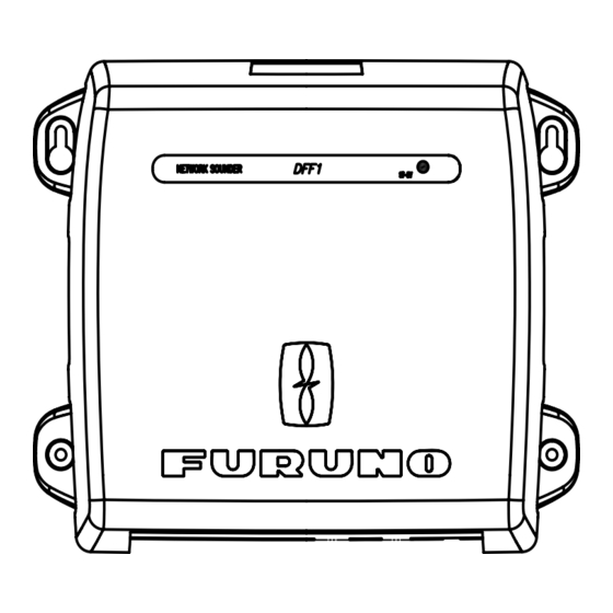
Page 8: Network Sounder
• Leave slack in cables for maintenance and servicing ease. • A magnetic compass will be affected if the network sounder is placed too close to it. Observe the compass safe distances noted in the safety instructions to prevent dis- turbance to the magnetic compass. -
Page 9: Transducer 520-5Psd, 520-5Msd
Transducer 520-5PSD, 520-5MSD 1.3.1 Mounting location .The performance of this sounder is directly related to the mounting location of the transducer, especially for high-speed cruising. The installation should be planned in advance, keeping the standard cable length and the following factors in mind: •... -
Page 10: Acceptable Mounting Locations
1.3.2 Acceptable mounting locations Deep-V hull * Position 1/2 to 1/3 length of the hull from stern. * 15-30 cm from center line (inside first lifting strakes). Transducer mounting location on deep-V hull High speed V-planing hull Transducer mounting location on high speed V-planing hull * Within the wetted bottom area * Deadrise angle within 15°... -
Page 11: Installation Procedure
1.3.3 Installation procedure 1. With the boat hauled out of the water, mark the location selected for mounting the transducer on the bottom of the hull. If the hull is not level within 15° in any direction, fairing blocks made out of teak should be used between the transducer and hull, both inside and outside, to keep the transducer face parallel with the water line. -
Page 12: Transducer 525-5Pwd (Transom Mount)
Transducer 525-5PWD (transom mount) This type of mounting is very commonly employed for outboard motor boats. Do not use this method on an inboard motor boat because turbulence is created by the pro- peller ahead of the transducer. There are two methods of installation: flush with hull (for flat hulls) and projecting from hull (for deep V-hulls). -
Page 13: Installation For Deep-V Hulls
1.4.2 Installation for deep-V hulls This method is employed on deep-V hulls and provides good performance because the effects of air bubbles are minimal. Install the transducer parallel with water surface; not flush with hull. If the boat is placed on a trailer care must be taken not to damage the transducer when the boat is hauled out of the water and put on the trailer. -
Page 14: Inside Hull Mount
Inside Hull Mount This mounting method is available for FRP boats. 1.5.1 Necessary tools You will need the following tools: • Sandpaper (#100) • Silicone sealant • Silicone grease 1.5.2 Remarks on installation • Turn off the engine and anchor the boat while installing the equipment. •... -
Page 15: Installation Procedure
1.5.4 Installation procedure 1. Clean the transducer face to remove any foreign material. Lightly roughen the transducer face with #100 sandpaper. Also, roughen the inside of the hull where the transducer is to be mounted. 2. Warm the silicone sealant to 40°C before usage to soften it. Coat the transducer face and mounting location with silicone sealant. -
Page 16: Optional Water Temperature Sensor St-02Msb, St-02Psb
Optional Water Temperature Sensor ST-02MSB, ST-02PSB Select a suitable mounting location considering the following points: • Select a mid-boat flat position. The sensor does not have to be installed perfectly perpendicular. The sensor must not be damaged in dry-docking operation. •... -
Page 17: Optional Temperature Sensors
Optional Temperature Sensors 1.7.1 Transom mount temperature sensor T-02MTB • Fix the cable at a convenient location with cable clamp. • When the cable is led in through the transom board, make a hole of approx. 17 mm in diameter to pass the connector. After passing the cable, fill the hole with a seal- ing compound. -
Page 18: Thru-Hull Temperature Sensor T-02Msb, T-03Msb
1.7.2 Thru-hull temperature sensor T-02MSB, T-03MSB Select a suitable mounting location considering the following points: • Select a mid-boat flat position. The sensor does not have to be installed perfectly perpendicular. However, the location should not be such that the transducer may be damaged when the boat is dry-docked. -
Page 19: Optionial Triducers
Optional Triducers 1.8.1 Thru-hull triducer 525ST-MSD See section 1.2 for how to install the 525ST-MSD. 133 mm 1.8.2 Transom mount triducer 525ST-PWD Pre-test for speed and temperature Connect the sensor to the instrument and spin the paddlewheel. Check for a speed reading and the approximate air temperature. - Page 20 • Straight edge • Marine sealant • Pencil • Zip-ties • Water-based antifouling paint (mandatory in salt water). Mounting location To ensure the best performance, the sensor must be submerged in aeration-free and turbulence-free water. Mount the sensor close to the centerline of the boat. On slower heavier displacement hulls, positioning it farther from the centerline is acceptable.
- Page 21 Installation of bracket 1. Cut out the installation template (enclosed with transducer) along the dotted line. 2. At the selected location, position the template, so the arrow at the bottom is aligned with the bottom edge of the transom. Being sure the template is parallel to the waterline, tape it in place.
- Page 22 Attaching the sensor to the bracket 1. If the retaining cover near the top of the bracket is closed, open it by depressing the latch and rotating the cover downward. Step 1 Retaining cover Step 3 Attaching the sensor to the bracket 2.
- Page 23 19 ° -22 ° transom angle (small aluminum and fiberglass boats): Position the shim with the tapered end up. 2°-10° 11° transom angle transom angle shim with taper down parallel 12°-18° transom angle angle reversed Sensor position and transom angle 3.
- Page 24 Cable routing Route the sensor cable over the transom, through a drain hole, or thorough a new hole drilled in the transom above the waterline. Never cut the cable or remote the connector; this will void the warranty. Always wear safety goggles and a dust mask.
-
Page 25: Wiring
12-24 VDC 1.1-0.4 A MODE SW 1 2 3 4 NETWORK Black TRANSDUCER BATTERY 12-24 VDC DFF1, rear view CAUTION Ground the equipment to prevent mutual interference. ) to make the ground connection at the network 3 GND GROUND WIRE IV-1.25sq... -
Page 26: Optional Temperature/Speed Sensor, Temperature Sensor
MJ-A10SPF MJ-A6SRMD Tape connector with self-vulcanizing tape and then vinyl tape to waterproof connector. Bind tape end with cable tie. Transducer connector MJ-A10SPF TEMP TEMP0V SPD0V/ SHIELD XDR port on the DFF1 XDR+ XDR SHIELD XDR- MJ-A10SRMD... -
Page 27: Wiring Optional 1 Kw Transducer
Matching Box MB-1100 Code No. 000-041-000 000-538-113 000-516-650 Shield Vinyl tube Taping Fabrication of transducer cable TO NETWORK SOUNDER (Cable is fitted with 8P connector. 8P-10P converter connector is required.) Remarks Cable w/8P connector sup- plied for connection to net- work sounder... - Page 28 This page is intentionally left blank.
-
Page 29: Initial Settings, Operation
#1 segment of DIP SW S2 on the pcb 02P6353 inside the network sounder. 1. Detach the power cable. 2. Detach the cover of the DFF1; grasp the cover at opposing sides with hands, pull outward slightly and lift up to detach. -
Page 30: Mode Sw
MODE SW The MODE switch provides the functions described in the table below. Remove the rubber cap to access the switch and set switches with a plastic screwdriver or the like. NETWORK Function, description Power from NavNet (Default:ON) IP number Default: OFF) (Currently no use) Factory testing... -
Page 31: Operation Check (Led)
Operation Check (LED) The network sounder is powered on/off from ship’s switchboard. The LED on the net- work sounder lights or flashes according to equipment state, as described in the table below. LED state Lighting continuously* Flashing every two seconds... - Page 32 This page is intentionally left blank.
-
Page 33: Maintenance
MAINTENANCE Maintenance Regular maintenance is essential for good performance. Check the items listed in the table below monthly to help keep your equipment in good shape for years to come. Item Transducer cable Power cable, transducer cable plug Ground Power supply voltage Cleaning the network sounder’s cabinet Transducer... -
Page 34: Replacing The Fuse
If the equipment cannot be powered, a fuse may have blown. Find out the cause for blown fuse before replacing a fuse. If a fuse blows again after replacement, contact a FURUNO agent or dealer for advice. Use the proper fuse. - Page 35 (IEC60529) 3.4. Vibration (IEC 60945 Ed4) 4. COATING COLOR 4.1. Main Unit DFF1 600 W/ 1 kW rms nominal, 1 kW requires optional MB-1100 50 kHz or 200 kHz, 50/200 kHz exchangeable Wide dynamic linear amp (double superheterodyne) Ethernet 100/10BASE-TX Range (m) PRR ( /min.)
-
Page 36: Packing List
DFF1-J/E N A M E ユニット UNIT ネットワーク魚探 NETWORK SOUNDER 予備品 SPARE PARTS ヒューズ FUSE 工事材料 INSTALLATION MATERIALS ケーブル組品MJ POWER CABLE ASSY. ケーブル組品MJ CABLE ASSY. +トラスタッピンネジ 1シュ SELF-TAPPING SCREW 図書 DOCUMENT 取扱説明書 OPERATOR'S MANUAL コ-ド番号末尾の[**]は、選択品の代表コードを表します。 CODE NUMBER ENDING WITH "**" INDICATES THE CODE NUMBER OF REPRESENTATIVE MATERIAL. - Page 39 XDR- SHIELD XDR+ TEMP0V TEMP SPD0V/SHIELD +12V TEMP0V TEMP XDR- SHIELD XDR+ TEMP0V TEMP SPD0V/SHIELD +12V XDR- SHIELD XDR+ 8m±0.5m TEMP0V TEMP SPD0V/SHIELD +12V COMMON COMMON 200K MJ-A10SRMD MJ-A6SRMD MJ-A6SRMD クロ ミドリ アオ アカ 200K COMMON COMMON...
- Page 40 Printed in Japan All rights reserved. All rights reserved. Pub. No. OME-20360 Pub. No. OME-20360 ( ( HIMA HIMA ) ) DFF1 DFF1 The paper used in this manual is elemental chlorine free. FURUNO Authorized Distributor/Dealer FURUNO Authorized Distributor/Dealer FIRST EDITION : FIRST EDITION : FEB.
Need help?
Do you have a question about the DFF1 and is the answer not in the manual?
Questions and answers