Table of Contents
Advertisement
Advertisement
Table of Contents

Related Manuals for Furuno DFF1


Summary of Contents for Furuno DFF1
- Page 1 OPERATOR'S MANUAL NETWORK SOUNDER DFF1 MODEL www.furuno.com...
-
Page 3: Important Notices
How to discard a used battery Some FURUNO products have a battery(ies). To see if your product has a battery, see the chapter on Maintenance. Follow the instructions below if a battery is used. Tape the + and - terminals of battery before disposal to prevent fire, heat generation caused by short circuit. - Page 4 Turn off the power immediately if you Do not remove these labels. If a label is missing feelthe equipment is acting abnormally. or illegible, contact a FURUNO agent or dealer about replacement. If the equipment is very warm or is...
- Page 5 Safety instructions for the installer WARNING CAUTION The transducer cable must be handled Do not open the equipment. carefully, following the guidelines below. Only qualified personnel should work inside the equipment. • Keep fuels and oils away from the cable. Turn off the power before beginning •...
-
Page 6: Table Of Contents
TABLE OF CONTENTS SYSTEM CONFIGURATION ................... v 1. MOUNTING ......................... 1 1.1 Equipment Lists ........................1 1.2 Network Sounder........................2 1.3 Transducer 520-5PSD, 520-5MSD..................3 1.3.1 Mounting location .......................3 1.3.2 Acceptable mounting locations ..................4 1.3.3 Installation procedure ....................4 1.4 Transducer 525-5PWD (transom mount) ................6 1.4.1 Installation for flat hulls....................6 1.4.2 Installation for deep-V hulls..................7 1.4.3 Transducer preparation....................7... -
Page 7: System Configuration
SYSTEM CONFIGURATION This sounder can be connected to NavNet/NavNet vx2*, NavNet 3D (MFD8/12/BB) and NavNet TZtouch (TZT9/14). Network Sounder NavNet series DFF1 Radar Plotter NavNet series Radar HUB* Plotter Radar Plotter Radar Plotter Matching Box 1 kW Rectifier MB-1100 12-24 VDC... -
Page 8: Mounting
MOUNTING Equipment Lists Standard supply Name Type Code No. Remarks Network Sounder DFF1 Spare Parts SP02-05201 001-007-860 1 set Fuse Installation Materials CP02-08100 000-010-153 1 set Power cable, LAN cable, Self-tapping screws Optional supply Name Type Code No. Remarks Matching Box... -
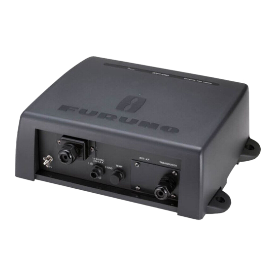
Page 9: Network Sounder
Ø FIXING HOLES 230±1 # MORE THAN 70 # MORE THAN 70 NOTE: The DFF1 is not waterproofed. Mount the unit so that the cable entrance does NOT face upward, to reduce the chance of water leakage into the unit. -
Page 10: Transducer 520-5Psd, 520-5Msd
Transducer 520-5PSD, 520-5MSD 1.3.1 Mounting location .The performance of this sounder is directly related to the mounting location of the transducer, especially for high-speed cruising. The installation should be planned in advance, keeping the standard cable length and the following factors in mind: •... -
Page 11: Acceptable Mounting Locations
1.3.2 Acceptable mounting locations Deep-V hull * Position 1/2 to 1/3 length of the hull from stern. * 15-30 cm from center line (inside first lifting strakes). Transducer mounting location on deep-V hull High speed V-planing hull * Within the wetted bottom area * Deadrise angle within 15°... -
Page 12: Installation Procedure
1.3.3 Installation procedure 1. With the boat hauled out of the water, mark the location selected for mounting the transducer on the bottom of the hull. If the hull is not level within 15° in any direction, fairing blocks made out of teak should be used between the transducer and hull, both inside and outside, to keep the transducer face parallel with the water line. -
Page 13: Transducer 525-5Pwd (Transom Mount)
Transducer 525-5PWD (transom mount) This type of mounting is very commonly employed for outboard motor boats. Do not use this method on an inboard motor boat because turbulence is created by the pro- peller ahead of the transducer. There are two methods of installation: flush with hull (for flat hulls) and projecting from hull (for deep V-hulls). -
Page 14: Installation For Deep-V Hulls
1.4.2 Installation for deep-V hulls This method is employed on deep-V hulls and provides good performance because the effects of air bubbles are minimal. Install the transducer parallel with water surface; not flush with hull. If the boat is placed on a trailer care must be taken not to damage the transducer when the boat is hauled out of the water and put on the trailer. -
Page 15: Inside Hull Mount
Inside Hull Mount This mounting method is available for FRP boats. 1.5.1 Necessary tools You will need the following tools: • Sandpaper (#100) • Silicone sealant • Silicone grease 1.5.2 Remarks on installation • Turn off the engine and anchor the boat while installing the equipment. •... -
Page 16: Installation Procedure
1.5.4 Installation procedure 1. Clean the transducer face to remove any foreign material. Lightly roughen the transducer face with #100 sandpaper. Also, roughen the inside of the hull where the transducer is to be mounted. 2. Warm the silicone sealant to 40°C before usage to soften it. Coat the transducer face and mounting location with silicone sealant. -
Page 17: Optional Water Temperature Sensor St-02Msb, St-02Psb
Optional Water Temperature Sensor ST-02MSB, ST-02PSB Select a suitable mounting location considering the following points: • Select a mid-boat flat position. The sensor does not have to be installed perfectly perpendicular. The sensor must not be damaged in dry-docking operation. •... -
Page 18: Optional Temperature Sensors
Optional Temperature Sensors 1.7.1 Transom mount temperature sensor T-02MTB • Fix the cable at a convenient location with cable clamp. • When the cable is led in through the transom board, make a hole of approx. 17 mm in diameter to pass the connector. After passing the cable, fill the hole with a seal- ing compound. -
Page 19: Thru-Hull Temperature Sensor T-02Msb, T-03Msb
1.7.2 Thru-hull temperature sensor T-02MSB, T-03MSB Select a suitable mounting location considering the following points: • Select a mid-boat flat position. The sensor does not have to be installed perfectly perpendicular. However, the location should not be such that the transducer may be damaged when the boat is dry-docked. -
Page 20: Optionial Triducers
Optional Triducers 1.8.1 Thru-hull triducer 525STID-MSD See section 1.2 for how to install the 525STID-MSD. φ 79 mm 133 mm ° 2.00 Thread 7 mm φ 51 mm Unit: mm 140 mm 27 mm 1.8.2 Transom mount triducer 525STID-PWD Pre-test for speed and temperature Connect the sensor to the instrument and spin the paddlewheel. - Page 21 • Straight edge • Marine sealant • Pencil • Zip-ties • Water-based antifouling paint (mandatory in salt water). Mounting location To ensure the best performance, the sensor must be submerged in aeration-free and turbulence-free water. Mount the sensor close to the centerline of the boat. On slower heavier displacement hulls, positioning it farther from the centerline is acceptable.
- Page 22 Installation of bracket 1. Cut out the installation template (enclosed with transducer) along the dotted line. 2. At the selected location, position the template, so the arrow at the bottom is aligned with the bottom edge of the transom. Being sure the template is parallel to the waterline, tape it in place.
- Page 23 Attaching the sensor to the bracket 1. If the retaining cover near the top of the bracket is closed, open it by depressing the latch and rotating the cover downward. Step 1 Step 2 Latch Pivot arm (2) Retaining Slot (2) cover Step 3 Step 4...
- Page 24 19 ° -22 ° transom angle (small aluminum and fiberglass boats): Position the shim with the tapered end up. 2°-10° 11° transom angle 19°-22° transom NO SHIM transom angle angle shim with shim with taper up taper down parallel parallel parallel 12°-18°...
- Page 25 Cable routing Route the sensor cable over the transom, through a drain hole, or thorough a new hole drilled in the transom above the waterline. Never cut the cable or remote the connector; this will void the warranty. Always wear safety goggles and a dust mask.
-
Page 26: Wiring
Shield (green) TRANSDUCER BATTERY 12-24 VDC DFF1, rear view Ground Connect the ground wire (1.25sq) to ship's ground to prevent interference to the pic- ture. Shorten the ground wire as much as possible. For FRP vessels, install a ground plate that measures about 20 cm by 30 cm on the outside of the hull bottom to provide a ground point. -
Page 27: Optional Temperature/Speed Sensor, Temperature Sensor
(Type: 02S4147, Code No.: 000-141-082, option). MJ-A6SRMD MJ-A10SPF SHIELD TEMP TEMP TEMP0V TEMP0V/SPD0V SPD0V/ SHIELD Temperature sensor OR XDR port on the Temperature/ DFF1 speed sensor MJ-A10SRMD XDR+ XDR SHIELD XDR- Transducer XDR+ XDR SHIELD XDR- Connection of temperature/speed sensor Connect to XDR port... -
Page 28: Wiring Optional 1 Kw Transducer
Wiring Optional 1 kW Transducer To connect optional transducer 50B-6, 50B-6B, 50B-9B, 200B-5, 200B-5S, 50/200-1T or 50/200-12M, the optional Matching Box MB-1100 is required. Jumper block setting J2: Full power output 02P6168 50kHz J1: Reduced power output 50B-6/6B Shield SHIELD 50B-9B TO NETWORK SOUNDER 200kHz... -
Page 29: Initial Settings, Operation
For NavNet/NavNet vx2 1. Detach the power cable. 2. Detach the cover of the DFF1; grasp the cover at opposing sides with hands, pull outward slightly and lift up to detach. 3. Loosen three screws fixing the inside cover, and slide cover forward to detach it. -
Page 30: Mode Sw
MODE SW The MODE switch provides the functions described in the table below. Remove the rubber cap to access the switch and set switches with a plastic screwdriver or the like. 12-24 VDC 1.1-0.4 A 3 GND MODE SW 1 2 3 4 NETWORK #1: ON #2: OFF... -
Page 31: Operation Check (Led)
NavNet Flashing every two seconds Normal operation Flashing every four seconds Factory test mode * T he LED lights for approximately 20 seconds after turning on the power while the equipment is being initialized . DFF1, top view... -
Page 32: Maintenance
MAINTENANCE WARNING Do not open the equipment unless totally familiar with electrical circuits and service manual. Only qualified personnel should work inside the equipment. Maintenance Regular maintenance is essential for good performance. Check the items listed in the table below monthly to help keep your equipment in good shape for years to come. Checking Item Action... -
Page 33: Replacing The Fuse
If the equipment cannot be powered, a fuse may have blown. Find out the cause for blown fuse before replacing a fuse. If a fuse blows again after replacement, contact a FURUNO agent or dealer for advice. WARNING Use the proper fuse. - Page 34 FURUNO DFF1 SPECIFICATIONS OF THE NETWORK SOUNDER DFF1 1. GENERAL 1.1. Output Power 600 W/ 1 kW rms nominal, 1 kW requires optional MB-1100 1.2. TX Frequency 50 kHz or 200 kHz, 50/200 kHz exchangeable 1.3. Amplifier type Wide dynamic linear amp (double superheterodyne) 1.4.
-
Page 35: Packing List
PACKING LIST 02GB-X-9851 -5 DFF1-J/E N A M E DESCRIPTION/CODE № O U T L I N E Q'TY ユニット UNIT ネットワーク魚探 DFF1 NETWORK SOUNDER 000-010-154-00 予備品 SPARE PARTS SP02-05201 ヒューズ FGBO-A 125V 3A PBF GLASS TUBE FUSE 000-155-850-10 工事材料 INSTALLATION MATERIALS CP02-08100 ケーブル(組品)LAN... - Page 39 When a claim is made, FURUNO has a right to choose whether with other electronic devices. The imported product may also be to repair the product or replace it.
- Page 40 24 months from installation date provided the work is done by Furuno U.S.A., Inc. or an AUTHORIZED Furuno dealer during normal shop hours and within a radius of 50 miles of the shop location.
- Page 41 (title and/or number and date of issue of the standard(s) or other normative document(s)) For assessment, see • EMC Test Report FLI 12-06-062 of 11 December 2006 prepared by Furuno Labotech International Co., Ltd. This declaration is issued according to the Council Directive of 3 May 1989 on the approximation of the laws of the Member States relating to electromagnetic compatibility (89/336/EEC).
- Page 42 This page is intentionally left blank .
- Page 44 Nishinomiya, 662-8580, JAPAN A : FEB 2007 Printed in Japan All rights reserved. E1 : JUN . 27, 2012 Pub. No. OME-20360-E1 *00016495714* *00016495714* (YOTA ) DFF1 *00016495714* *00016495714* * 0 0 0 1 6 4 9 5 7 1 4 *...
Need help?
Do you have a question about the DFF1 and is the answer not in the manual?
Questions and answers