Table of Contents
Advertisement
Quick Links
Professional Remote Weather Station
Table of Contents
1.
Introduction ................................................ 2
2.
Intended use .............................................. 2
Weather Station ......................................... 2
System requirements for PC use................ 3
Features of the base station ....................... 3
Features of the thermo-hygro sensor.......... 4
Features of the wind sensor ....................... 4
Features of the rain sensor......................... 4
3.
Safety Notes .............................................. 4
4.
Packaged contents..................................... 6
5.
Setting up................................................... 7
6.
wireless 433MHz ....................................... 9
7.
LCD overview........................................... 11
8.
Function test ............................................ 13
9.
Mounting .................................................. 14
10.
Resetting & factory settings...................... 16
11.
Function description ................................. 18
12.
Operation keys......................................... 21
13.
Basic programming modes....................... 23
14.
MIN/MAX programming modes ................ 24
15.
Alarm programming modes ...................... 26
16.
Auto-memory for stored values ................ 34
17.
Accessories: extensions cables................ 35
18.
Changing batteries ................................... 36
19.
Problems and interference with operation 37
20.
Transmission range.................................. 38
21.
Cleaning and maintenance....................... 38
22.
Specifications........................................... 39
23.
Warranty Information................................ 41
This Operation Manual is part of this product and should be kept
in a safe place for future reference. It contains important notes on
setup and operation.
Please see www.heavyweather.info for a complete IM, FAQ and
downloads of the most current software.
Operation Manual
1
Page
Advertisement
Table of Contents

Related Manuals for La Crosse Technology WS-2317


Summary of Contents for La Crosse Technology WS-2317
-
Page 1: Table Of Contents
Operation Manual Professional Remote Weather Station Table of Contents Page Introduction ..........2 Intended use ..........2 Weather Station ......... 2 System requirements for PC use....3 Features of the base station ....... 3 Features of the thermo-hygro sensor..4 Features of the wind sensor ....... -
Page 2: Introduction
Introduction Thank you for purchasing this Professional Remote Weather Station. Designed for everyday use, the weather station will prove to be an asset of great value for your personal use in the home or office. Please read this instruction manual thoroughly to fully understand the correct operation of your weather station and benefit from its unique features. -
Page 3: System Requirements For Pc Use
This weather station is designed to work easily with your PC, simply connect and disconnect the PC cable at any time. System Requirements for PC use: The minimum system requirement for use of this “Heavy Weather” software is: Operating system: Windows 98 or above Processor: Pentium 166 MHz or above RAM: 32MB of RAM or above Hard disk: 20MB free space... -
Page 4: Features Of The Thermo-Hygro Sensor
Weather tendency indicator • Storm warning alarm • EL back light • Simultaneous display of all weather data with individual • settings by the user COM port for easy connection to your PC • All the weather data from the base station and up to 175 •... - Page 5 this instruction manual, the manufacturer and supplier cannot be held liable. For reasons of safety and operation, alterations to this • device are strictly prohibited. To operate the weather station, use only supplied • adaptor and batteries of the recommended type. Do not leave discharged batteries in the device as these •...
-
Page 6: Packaged Contents
Packaged Contents Before setting up, carefully unpack the contents onto a table or flat surface and check that the following are complete: Item: Consisting Fittings: Illustration: Base • Main unit • AD/DC 120V Station power Adaptor - optional use (included) Thermo •... -
Page 7: Setting Up
Heavy CD-Rom • 6.5ft PC cable weather format for PC (English connection - softwar version only) optional use (included) Setting up First, choose to use the adaptor (included in this set) or batteries for operation. Both these methods allow for operation using wireless 433MHz transmission or cable connection between the base station and the sensors and setting up for both methods is as follows:... - Page 8 Setting up using batteries: Thermo-Hygro Sensor Sensor Battery Cover sockets Battery Compartment Sensor sockets Important: To avoid operating problems, please take note of battery polarity if inserting any batteries Pull away the rain cover of the thermo-hygro sensor to reveal the three sockets (for the wind sensor, rain sensor and the base station) Connect the attached cables of wind and rain sensors to the corresponding sockets of the thermo-hygro sensor by...
-
Page 9: Operation Using Cable Connection Or Wireless 433Mhz
Setting up using the AC adaptor: Power up all the sensors as described in setting up using batteries above Using the AC adaptor (included), plug it into the power outlet and power up the base station by inserting the adaptor jack into the DC 6.0V socket located on the side of the base station Every time the thermo-hygro sensor is powered up (for example after a change of batteries), a random security code... - Page 10 433MHz transmission and will result in higher power consumption. Batteries will have a shorter life span for cable connection compared to using 433MHz wireless transmission. To operate using cable connection, simply use the enclosed 32ft cable and connect the thermo-hygro sensor to the base station.
-
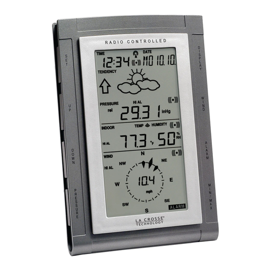
Page 11: Lcd Overview
simply press and hold the PLUS (+) key for 2 seconds and a short beep will sound to synchronize the base station to sensors. Without being synchronized, weather data will not be received. LCD Overview The following illustration shows the full segments of the LCD for description purposes only and will not appear like this during normal operation and use. -
Page 12: Function Test
15. 24h, 1h or total hour Low battery indicator WWVB radio controlled display 16. Humidity display as RH% time icon 17. Rainfall units (inch or mm) Date display 18. Temperature display units Time zone display (ºC or ºF) Date, seconds, alarm 19. - Page 13 LCD. In this case, check that all cables are correctly inserted into the correct sockets and/or check the batteries in the outdoor thermo-hygro sensor and press and hold the PLUS (+) key for 2 seconds, a short beep will sound to synchronize the base station to the sensors otherwise no weather data will be received.
-
Page 14: Mounting
NOTE: For reception of WWVB time/date signal, do not mount the base station closer than 5 feet from a computer, florescent lights or other electrical appliances. Do not mount the base station on a wall that has metal heat/AC ductwork in the wall behind the base station. - Page 15 For accurate results, the rain sensor should be securely mounted onto a horizontal surface about 2-3ft above the ground and in an open area away from trees or other coverings where rainfall may be reduced causing inaccurate readings. When securing into place, check that rain excess will not collect and store at the base of the unit but can flow out between the base and the mounting surface (test by pouring clean water).
-
Page 16: Resetting & Factory Settings
To wall mount, use the 2 screws to affix the wall bracket to the desired wall, plug in the thermo-hygro sensor to the bracket and secure both parts by the use of the supplied screw and ensure that the cables from the wind and rain sensors are correctly plugged in otherwise data transmission errors could occur. - Page 17 Time zone -5 ET Alarm time 12:00 am Relative air pressure 29.91 inHg Weather-picture 0.09 inHg threshold LCD contrast level 5 (1-8 levels) Rainfall per impulse 0.0204 inches Storm alarm 0.09 inHg Relative air pressure 28.34 inHg 30.71 inHg alarm (low) (high) Indoor temperature...
-
Page 18: Function Description
Function Description of the Weather Station After setting up, the following data will be displayed in different sections on the LCD. If this is not the case please observe the notes on “Interferences” below. LCD Section 1: Time, date, seconds, time zone, weather forecasting icons with tendency arrows, air pressure, and respective alarms sections... - Page 19 Notes to inHg sensitivity setting for weather forecasting: The inHg pressure sensitivity can be set to suit the user’s requirement for weather forecasting from 6 inHg, 9 inHg to 12 inHg (see Basic Programming below). For areas that experience frequent changes in air pressure (which does not necessarily reflect a change in the weather) requires a higher inHg setting compared to an area where the air pressure is stagnant.
- Page 20 Outdoor dew point Rainfall 24h Rainfall 1h Rainfall total. Notes to Dewpoint and Windchill: Air can at a certain temperature only carry a certain amount of water (water vapor), which also increases and decreases with temperature. If the air temperature decreases below the dew point (saturation point), the excessive water vapor will condense and fall out in form of dew, fog or rain.
-
Page 21: Operation Keys
Operation keys The base station has 8 keys for easy operation. Please refer to the following table for use and function of each key: Further descriptions of the key functions with regard to their immediate range of application can be found in the Programming modes: SET - key - In normal mode to enter the manual... - Page 22 - Wind speed - Wind direction - Wind direction display in degrees ALARM - - In normal mode to enter the alarm programming mode - In alarm programming mode to select the following setting modes: - Time alarm setting - Indoor temperature alarm (high & low) - Outdoor temperature alarm (high &...
-
Page 23: Basic Programming Modes
enable/disable the buzzer alarm (long pressing) - To decrease the values in the setting modes - In basic programming mode audible storm alarm ON/OFF - To snooze the alarms off 24 hours when the alarm is sounding - In MIN/MAX modes to reset recorded values and recorded dates and times *Press any key to activate the EL backlight Basic Programming Modes... -
Page 24: Min/Max Programming Modes
12. Storm warning sensitivity setting 9, 12, 15, 18, 21, 24, 29 inHg (default 9 inHg) 13. Audible storm alarm On/OFF (default ON) To change any of the above values, once you are in the setting mode, use the PLUS (+) or MINUS (-) keys to select the values followed by the SET key to enter the next setting. - Page 25 received. Now press the MIN/MAX key to toggle from the minimum and maximum readings and the time and dates the records were received are also shown. Still in the MIN/MAX mode (where the time and date for a value are shown), press the DISPLAY key to move through each respective unit as follows: •...
-
Page 26: Alarm Programming Modes
rainfall total value to zero and the time recording to current time. The second case is Rainfall 24h or 1h, which records maximum rain count only for these respective times. Pressing the MINUS (-) key in either of these two modes will reset the rain count to the current rain count and time and date. - Page 27 Time alarm setting Press the ALARM key to enter the normal time alarm Press and hold the SET key to enter the alarm hour time set mode (the hour digits will flash) and set the desired hour by using the PLUS (+) or MINUS (-) keys Press the SET key to enter the alarm minute time set mode (the minutes digits will flash) and set the desired minutes using the PLUS (+) or MINUS (-) keys...
- Page 28 4) Press ALARM key to confirm and press the MIN/MAX key to return to the normal display mode or press the ALARM once more to toggle to the outdoor temperature low alarm set mode. 5) Press and hold the SET key to enter the outdoor temperature low setting values (digits will start flashing) and set the desired outdoor temperature low by using the PLUS (+) or MINUS (-) keys.
- Page 29 4) Press ALARM key to confirm and press the MIN/MAX key to return to the normal display mode or press the ALARM key once more to toggle to the outdoor humidity low alarm set mode. 5) Press and hold the SET key to enter the outdoor humidity low setting values (digits will start flashing) and set the desired outdoor humidity low by using the PLUS (+) or MINUS (-) keys...
- Page 30 key once more to toggle to the dew point low alarm set mode. 5) Press and hold the SET key to enter the dew point low setting values (digits will start flashing) and set the desired dew point low by using the PLUS (+) or MINUS (-) keys 6) Press ALARM key to confirm and press the MIN/MAX key to return the normal display mode or press the ALARM once more to toggle to another alarm setting mode.
- Page 31 key once more to toggle to the pressure low alarm set mode. 5) Press and hold the SET key to enter the pressure low setting values (digits will start flashing) and set the desired pressure low by using the PLUS (+) or MINUS (-) keys 6) Press ALARM key to confirm and press the MIN/MAX key to return to the normal display mode or press the ALARM once more to toggle to another alarm setting mode.
- Page 32 Storm warning alarm setting Unlike the other weather alarms, the storm warning alarm is set by entering the main manual setting mode as follows: Press the SET key to enter the manual setting mode Continue to press the SET key until the Storm warning icon flashes (tendency arrow flashing downwards with the pressure values flashing) Set the desired inHg pressure value (9, 12, 15, 18, 21,...
- Page 33 values against the MIN/MAX values reached. To deactivate the general weather alarm icon, press the ALARM key. Important When entering the alarm set mode for a specific weather or temperature condition, the corresponding alarm is automatically enabled (ON) when the SET key is pressed, regardless of its previous setting and the alarm value will flash to indicate that it has been activated.
-
Page 34: Auto-Memory For Stored Values
Rainfall 1h 0.0 inch 39.37 inch Wind 0.0 mph 111.8 mph Hysteresis To compensate for fluctuation of the measured data, which may cause the weather alarm to sound constantly if the measured reading is close to user set level, a hysteresis function has been implemented for each weather alarm. -
Page 35: Accessories: Extensions Cables
Weather picture threshold • Storm warning threshold • LCD contrast • Alarm time • Weather Alarm thresholds • State of alarms (enabled/disabled) • Rainfall total value and reset time/date • Accessories: adding cable extensions For your convenience, additional telephone cables to increase the connection distance between each of the units may be purchased from any reputable hardware store. -
Page 36: Changing Batteries
Note: It is important to keep all the connected extension heads away from rain, moisture and other extreme weather conditions as exposure can cause short circuits and damage to this item. Changing batteries Battery change only in the thermo-hygro-sensor: Open the battery cover Remove the old batteries and insert with new ones of the recommended type and replace the cover Once the sensor is powered up, press and hold the PLUS (+) - Page 37 Interferences and problems with operation Problem & cause Remedy Distance between Reduce distance between transmitters and transmitters and receiver to receiver too long. receive signal High shielding Find a different location for materials between the sensors and/or receiver. See units (thick walls, also Item ‘Transmission steel, concrete, Range’...
-
Page 38: Transmission Range
Quite frequently interferences are only of a temporary nature and may be easily overcome. If there are wireless headsets, remote babysitters or other devices working on 433MHz in your house or in the vicinity, their switch-on time is mostly limited. Furthermore most of these devices allow the change to an interference- free frequency. -
Page 39: Specifications
Do not clean the funnel with the bottom half of the rain sensor attached nor the bottom part itself under running water. This may bear the danger of water entering the unit’s inner parts and cause damages. Do not immerse the base station in water. Should there be damage to this product, please do not attempt to make any repairs. - Page 40 With cable connection for data transmission: Measuring interval thermo-hygro sensor : 8 seconds Indoor data Pressure/ temperature : 4 times per minute Indoor Temperature Range : 14.2°F to + 139.8°F (shows “OFL” if outside range) Resolution : 0.2°F Measuring Range Rel. Humidity : 1% to 99% Resolution : 1% Measuring Range Air Pressure : 8.86 inHg to 32.45 inHg...
-
Page 41: Warranty Information
The owner must pay any shipping charges incurred in getting your La Crosse Technol- ogy, Ltd product to a La Crosse Technology, Ltd au- thorized service center. La Crosse Technology, Ltd will... - Page 42 Your La Crosse Technology, Ltd warranty covers all defects in material and workmanship with the following specified exceptions: (1) damage caused by accident, unreasonable use or neglect (including the lack of reasonable and necessary maintenance);...
- Page 43 For warranty work, technical support, or information contact: La Crosse Technology, Ltd 190 Main Street La Crescent, MN 55947 Phone: 507.895.7095 Fax: 507.895.2820 e-mail: support@lacrossetechnology.com (warranty work) sales@lacrossetechnology.com...
Need help?
Do you have a question about the WS-2317 and is the answer not in the manual?
Questions and answers