
Related Manuals for Black Box LGB710A


Summary of Contents for Black Box LGB710A
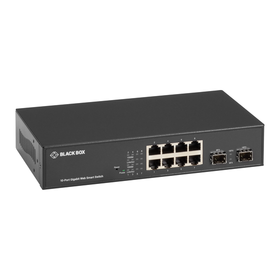
- Page 1 USER MANUAL LGB710A GIGABIT WEB SMART SWITCH, 10-PORT 24/7 TECHNICAL SUPPORT AT 1.877.877.2269 OR VISIT BLACKBOX.COM...
-
Page 2: Table Of Contents
NEED HELP? LEAVE THE TECH TO US LIVE 24/7 TABLE OF CONTENTS TECHNICAL SUPPORT 1.877.877.2269 SAFETY INFORMATION ..................................4 1. SPECIFICATIONS ................................... 5 2. OVERVIEW ...................................... 7 2.1 Introduction .......................................7 2.2 Features ........................................7 2.3 What’s Included ......................................7 2.4 Hardware Description ....................................8 2.4.1 Front Panel ........................................... - Page 3 NEED HELP? LEAVE THE TECH TO US LIVE 24/7 TABLE OF CONTENTS TECHNICAL SUPPORT 1.877.877.2269 APPENDIX A: IP CONFIGURATION FOR YOUR PC ........................33 APPENDIX B: REGULATORY INFORMATION ..........................36 B.1 FCC Class A Statement ..................................36 B.2 CE Notice ........................................36 B.3 NOM Statement .....................................37 APPENDIX C: DISCLAIMER/TRADEMARKS ..........................
-
Page 4: Safety Information
WARNING: Laser. If using an optical fiber SFP adapter when connecting to a Black Box switch or other device, the user must observe precautions for working with a Class 1 laser product. -
Page 5: Specifications
NEED HELP? LEAVE THE TECH TO US LIVE 24/7 CHAPTER 1: SPECIFICATIONS TECHNICAL SUPPORT 1.877.877.2269 TABLE 1-1. SWITCH SPECIFICATIONS Connectors 10/100/1000BASE RJ-45 Ports 100/1000BASE-X SFP Cage System Performance Packet Buffer 512 KB MAC Address Table Size Switching Capacity 20 Gbps Forwarding Rate 14,880 Mbps L2 Features... - Page 6 NEED HELP? LEAVE THE TECH TO US LIVE 24/7 CHAPTER 1: SPECIFICATIONS TECHNICAL SUPPORT 1.877.877.2269 TABLE 1-1 (CONTINUED). SWITCH SPECIFICATIONS General Power Input 100–240 VAC Max. Power Consumption 15 W (19) LEDs: Per unit: (1) Power; Indicators Per TP port: (1) 1000 M, (1) Link/Act; Per SFP slot: (1) FX LED Operating Temperature 32 to 113°F (0 to 45°C)
-
Page 7: Overview
Š Store and Forward: The switch uses this feature to maximize network performance while minimizing the propagation of bad network Š packets 2.3 WHAT’S INCLUDED Your package should include the following items. If anything is missing or damaged, contact Black Box Technical Support at 877- 877-2269 or info@blackbox.com. Š (1) Gigabit Web Smart Switch, 10-Port Š... -
Page 8: Hardware Description
(2) FX LEDs: (1) per SFP slot (2) FX LEDs: (1) per SFP slot ON: SFP module is connected OFF: SFP module is not connected Holds SFP modules. See Table 2-3 for compatible modules (2) SFP open slots from Black Box. 1.877.877.2269 BLACKBOX.COM... -
Page 9: Back Panel
NEED HELP? LEAVE THE TECH TO US LIVE 24/7 CHAPTER 2: OVERVIEW TECHNICAL SUPPORT 1.877.877.2269 2.4.2 BACK PANEL The back panel of this switch has a fan, power switch, and power connector. Figure 2-2 shows the back panel. Table 2-2 describes its components. -
Page 10: Compatible Sfp Modules
CHAPTER 2: OVERVIEW TECHNICAL SUPPORT 1.877.877.2269 2.4.3 COMPATIBLE SFP MODULES The following SFPs are available from Black Box to operate with the switch. TABLE 2-2. COMPATIBLE SFPS PRODUCT CODE DESCRIPTION LFP401 SFP - 155-Mbps, Extended Diagnostics, 850-nm Multimode Fiber, 2-km, LC... -
Page 11: Hardware Installation
We recommend purchasing SFP transceivers from Black Box. WARNING: Laser. If using an optical fiber SFP adapter when connecting to a Black Box switch or other device, the user must observe precautions for working with a Class 1 laser product. -
Page 12: Preparing For Management
NEED HELP? LEAVE THE TECH TO US LIVE 24/7 CHAPTER 4: PREPARING FOR MANAGEMENT TECHNICAL SUPPORT 1.877.877.2269 This section will explain how to manage the switch via the management web page. PREPARATION FOR WEB INTERFACE The management web page allows you to use a web browser (such as Microsoft Internet Explorer , Google Chrome™,... - Page 13 NEED HELP? LEAVE THE TECH TO US LIVE 24/7 CHAPTER 4: PREPARING FOR MANAGEMENT TECHNICAL SUPPORT 1.877.877.2269 6. The web browser will prompt you to log in. The default password for the configuration web page is admin. FIGURE 4-3. LOGIN SCREEN For more information, refer to Appendix A: IP Configuration for Your PC.
-
Page 14: Web Management
NEED HELP? LEAVE THE TECH TO US LIVE 24/7 CHAPTER 5: WEB MANAGEMENT TECHNICAL SUPPORT 1.877.877.2269 In Web Management: As mentioned in Chapter 4, this switch has a web-based management interface. You can make all settings and monitor system status with this management web page. Configuration/Monitor options included in the management web page can be divided into the following three categories, which will be discussed in detail in this chapter: Š... -
Page 15: Web Management - Configuration
NEED HELP? LEAVE THE TECH TO US LIVE 24/7 CHAPTER 5: WEB MANAGEMENT TECHNICAL SUPPORT 1.877.877.2269 As shown in the screen on the previous page, this switch’s setting options can be divided into three main categories: Š Configuration: Here you can make system configurations. The settings you can configure here include changing the IP address Š... - Page 16 NEED HELP? LEAVE THE TECH TO US LIVE 24/7 CHAPTER 5: WEB MANAGEMENT TECHNICAL SUPPORT 1.877.877.2269 FIGURE 5-3. SYSTEM CONFIGURATION SCREEN (CONTINUED) Š DHCP Enabled: Click the box to enable the DHCP client mode. Š NOTE: After enabling this function, you will have to reboot the switch by switching it off and on to apply the setting. Š...
-
Page 17: Configuration - Ports
NEED HELP? LEAVE THE TECH TO US LIVE 24/7 CHAPTER 5: WEB MANAGEMENT TECHNICAL SUPPORT 1.877.877.2269 5.2.2 CONFIGURATION — PORTS FIGURE 5-4. PORT CONFIGURATION SCREEN Š Enable Jumbo Frames: This switch provides more efficient throughput for large sequential data transfers by supporting jumbo frames on Š... -
Page 18: Configuration - Vlans
NEED HELP? LEAVE THE TECH TO US LIVE 24/7 CHAPTER 5: WEB MANAGEMENT TECHNICAL SUPPORT 1.877.877.2269 5.2.3 CONFIGURATION — VLANS FIGURE 5-5. ADD A VLAN VLAN stands for Virtual LAN, which is a logical network grouping that limits the broadcast domain and allows you to isolate network traffic so that only the members of the same VLAN group can communicate with each other. -
Page 19: Configuration - Aggregation
NEED HELP? LEAVE THE TECH TO US LIVE 24/7 CHAPTER 5: WEB MANAGEMENT TECHNICAL SUPPORT 1.877.877.2269 Š Modify: Press this button to modify the VLAN member port of the selected VLAN. Š Š Delete: Press this button to delete the selected VLAN. Š... -
Page 20: Configuration - Igmp Snooping
NEED HELP? LEAVE THE TECH TO US LIVE 24/7 CHAPTER 5: WEB MANAGEMENT TECHNICAL SUPPORT 1.877.877.2269 Port trunk allows multiple links to be bundled together and act as a single physical link for increased throughput. It provides load balancing,and redundancy of links in a switched inter-network. The link does not have an inherent total bandwidth equal to the sum of its component physical links. -
Page 21: Configuration - Mirroring
NEED HELP? LEAVE THE TECH TO US LIVE 24/7 CHAPTER 5: WEB MANAGEMENT TECHNICAL SUPPORT 1.877.877.2269 5.2.6 CONFIGURATION — MIRRORING FIGURE 5-11. MIRRORING CONFIGURATION SCREEN Port Mirroring is used on a network switch to send a copy of network packets seen on one port (or an entire VLAN) to a network monitoring connection on another switch port. - Page 22 NEED HELP? LEAVE THE TECH TO US LIVE 24/7 CHAPTER 5: WEB MANAGEMENT TECHNICAL SUPPORT 1.877.877.2269 FIGURE 5-13. PARAMETERS SCREEN Š Tx Interval: The switch periodically transmits LLDP frames to its neighbors to keep the network discovery information up-to-date. The Š...
-
Page 23: Configuration - Quality Of Service
NEED HELP? LEAVE THE TECH TO US LIVE 24/7 CHAPTER 5: WEB MANAGEMENT TECHNICAL SUPPORT 1.877.877.2269 5.2.8 CONFIGURATION — QUALITY OF SERVICE FIGURE 5-15. QOS MODE MENU This switch supports IEEE 802.1p and DSCP for QoS. Click the QoS Mode scroll-down menu to choose the QoS mode you would like to apply, and the QoS Configuration will change according. - Page 24 NEED HELP? LEAVE THE TECH TO US LIVE 24/7 CHAPTER 5: WEB MANAGEMENT TECHNICAL SUPPORT 1.877.877.2269 QoS DSCP FIGURE 5-17. QOS CONFIGURATION SCREEN In DSCP mode, packets are prioritized using the DSCP (Differentiated Services Code Point) value. The Differentiated Services Code Point (DSCP) is a six-bit field that is contained within an IP (TCP or UDP) header.
-
Page 25: Web Management - Monitoring
NEED HELP? LEAVE THE TECH TO US LIVE 24/7 CHAPTER 5: WEB MANAGEMENT TECHNICAL SUPPORT 1.877.877.2269 5.3 WEB MANAGEMENT — MONITORING 5.3.1 MONITORING — STATISTICS OVERVIEW FIGURE 5-18. STATISTICS OVERVIEW FOR ALL PORTS SCREEN This page displays the TX/RX Bytes/Frames/Errors of the switch. Buttons Š... -
Page 26: Monitoring - Detailed Statistics
NEED HELP? LEAVE THE TECH TO US LIVE 24/7 CHAPTER 5: WEB MANAGEMENT TECHNICAL SUPPORT 1.877.877.2269 5.3.2 MONITORING — DETAILED STATISTICS FIGURE 5-19. STATISTICS FOR PORT 1 SCREEN This page displays the detailed information for each port of the switch. Š... -
Page 27: Monitoring - Lldp Statistics
NEED HELP? LEAVE THE TECH TO US LIVE 24/7 CHAPTER 5: WEB MANAGEMENT TECHNICAL SUPPORT 1.877.877.2269 Š v2 Reports: Show the number of received v2 Report packets. Š Š v3 Reports: Show the number of received v2 Report packets. Š Š... -
Page 28: Monitoring - Lldp Table
NEED HELP? LEAVE THE TECH TO US LIVE 24/7 CHAPTER 5: WEB MANAGEMENT TECHNICAL SUPPORT 1.877.877.2269 5.3.5 MONITORING — LLDP TABLE FIGURE 5-22. LLDP NEIGHBOR TABLE SCREEN Š Local Port: The port on which the LLDP frame was received. Š Š... -
Page 29: Monitoring - Ping
NEED HELP? LEAVE THE TECH TO US LIVE 24/7 CHAPTER 5: WEB MANAGEMENT TECHNICAL SUPPORT 1.877.877.2269 5.3.6 MONITORING — PING FIGURE 5-23. PING PARAMETERS SCREEN Š Target IP Address: IP address of the host Š Š Count: Number of packets to send. (Range: 1–20) Š... -
Page 30: Web Management - Maintenance
NEED HELP? LEAVE THE TECH TO US LIVE 24/7 CHAPTER 5: WEB MANAGEMENT TECHNICAL SUPPORT 1.877.877.2269 5.4 WEB MANAGEMENT — MAINTENANCE 5.4.1 MAINTENANCE — WARM RESTART FIGURE 5-24. WARM RESTART SCREEN Here you can reboot the switch. Buttons Š Yes: Reboot the switch. Š... -
Page 31: Maintenance - Software Upload
NEED HELP? LEAVE THE TECH TO US LIVE 24/7 CHAPTER 5: WEB MANAGEMENT TECHNICAL SUPPORT 1.877.877.2269 5.4.3 MAINTENANCE — SOFTWARE UPLOAD FIGURE 5-26. SOFTWARE UPLOAD SCREEN Here you can upload firmware from your PC to the switch. Buttons Š Choose File: Press this button to choose the firmware file you would like to upload to the switch. Š... -
Page 32: Maintenance - Logout
NEED HELP? LEAVE THE TECH TO US LIVE 24/7 CHAPTER 5: WEB MANAGEMENT TECHNICAL SUPPORT 1.877.877.2269 Configuration Download Buttons Š Download: Press this button to save all the current settings as a “*.cfg” file. Š 5.4.5 MAINTENANCE — LOGOUT FIGURE 5-28. CONFIGURATION UPLOAD SCREEN Press the “Logout”... -
Page 33: Appendix A: Ip Configuration For Your Pc
NEED HELP? LEAVE THE TECH TO US LIVE 24/7 APPENDIX A: IP CONFIGURATION FOR YOUR PC TECHNICAL SUPPORT 1.877.877.2269 This appendix describes how to set the IP address of your PC so you can connect to the switch’s configuration web page. The configuration web page allows you to set system variables or monitor system status. - Page 34 NEED HELP? LEAVE THE TECH TO US LIVE 24/7 APPENDIX A: IP CONFIGURATION FOR YOUR PC TECHNICAL SUPPORT 1.877.877.2269 3. An Ethernet Status window will pop up. Click on the Properties button. FIGURE A-3. ETHERNET STATUS SCREEN 4. An Ethernet Properties window will pop up. Double-click on the Internet Protocol Version 4 (TCP/IPv4). FIGURE A-4.
- Page 35 NEED HELP? LEAVE THE TECH TO US LIVE 24/7 APPENDIX A: IP CONFIGURATION FOR YOUR PC TECHNICAL SUPPORT 1.877.877.2269 5. An Internet Protocol Version 4 (TCP/IPv4) Properties window will pop up. Set your PC’s IP address and subnet mask. By default, your switch’s IP address should be 192.168.2.1. You can set any IP address for the PC as long as it’s not the same as your switch’s IP address and is in the same network segment with your switch’s IP address.
-
Page 36: Appendix B: Regulatory Information
NEED HELP? LEAVE THE TECH TO US LIVE 24/7 APPENDIX B: REGULATORY INFORMATION TECHNICAL SUPPORT 1.877.877.2269 B.1 FCC CLASS A STATEMENT This equipment generates, uses, and can radiate radio-frequency energy, and if not installed and used properly, that is, in strict accordance with the manufacturer’s instructions, may cause interference to radio communication. -
Page 37: Nom Statement
NEED HELP? LEAVE THE TECH TO US LIVE 24/7 APPENDIX B: REGULATORY INFORMATION TECHNICAL SUPPORT 1.877.877.2269 B.3 NOM STATEMENT 1. Todas las instrucciones de seguridad y operación deberán ser leídas antes de que el aparato eléctrico sea operado. 2. Las instrucciones de seguridad y operación deberán ser guardadas para referencia futura. 3. -
Page 38: Appendix C: Disclaimer/Trademarks
C.1 DISCLAIMER Black Box Corporation shall not be liable for damages of any kind, including, but not limited to, punitive, consequential or cost of cover damages, resulting from any errors in the product information or specifications set forth in this document and Black Box Corporation may revise this document at any time without notice. - Page 39 NEED HELP? LEAVE THE TECH TO US LIVE 24/7 NOTES TECHNICAL SUPPORT 1.877.877.2269 __________________________________________________________________________________________________ __________________________________________________________________________________________________ __________________________________________________________________________________________________ __________________________________________________________________________________________________ __________________________________________________________________________________________________ __________________________________________________________________________________________________ __________________________________________________________________________________________________ _________________________________________________________________________________________________ __________________________________________________________________________________________________ __________________________________________________________________________________________________\ __________________________________________________________________________________________________ __________________________________________________________________________________________________ __________________________________________________________________________________________________ __________________________________________________________________________________________________ _________________________________________________________________________________________________ __________________________________________________________________________________________________ __________________________________________________________________________________________________ __________________________________________________________________________________________________ 1.877.877.2269 BLACKBOX.COM...
- Page 40 NEED HELP? LEAVE THE TECH TO US LIVE 24/7 TECHNICAL SUPPORT 1.877.877.2269 © COPYRIGHT 2019. BLACK BOX CORPORATION. ALL RIGHTS RESERVED. LGB710A_USER_REV1.PDF...
Need help?
Do you have a question about the LGB710A and is the answer not in the manual?
Questions and answers