Table of Contents
Advertisement
Quick Links
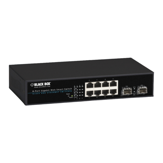
8-Port Gigabit Web Smart Switch
Provides eight 10/100/1000BASE-T(X) ports plus
two Gigabit SFP open slots.
Use where space is limited to upgrade network capacity.
Order toll-free in the U.S.: Call 877-877-BBOX (outside U.S. call 724-746-5500)
Customer
FREE technical support 24 hours a day, 7 days a week: Call 724-746-5500 or fax
Support
724-746-0746 • Mailing address: Black Box Corporation, 1000 Park Drive, Lawrence,
Information
PA 15055-1018 • Web site: www.blackbox.com • E-mail: info@blackbox.com
BLACK BOX
LGB708A-R2
LGB708A-R2-US
®
Advertisement
Table of Contents

Subscribe to Our Youtube Channel
Related Manuals for Black Box LGB708A-R2


Summary of Contents for Black Box LGB708A-R2
- Page 1 Order toll-free in the U.S.: Call 877-877-BBOX (outside U.S. call 724-746-5500) Customer FREE technical support 24 hours a day, 7 days a week: Call 724-746-5500 or fax Support 724-746-0746 • Mailing address: Black Box Corporation, 1000 Park Drive, Lawrence, Information PA 15055-1018 • Web site: www.blackbox.com • E-mail: info@blackbox.com...
- Page 2 FCC and IC RFI Statements/NOM Statement FEDERAL COMMUNICATIONS COMMISSION AND INDUSTRY CANADA RADIO FREQUENCY INTERFERENCE STATEMENTS This equipment generates, uses, and can radiate radio-frequency energy, and if not installed and used properly, that is, in strict accordance with the manufacturer’s instructions, may cause inter ference to radio communication. It has been tested and found to comply with the limits for a Class A computing device in accordance with the specifications in Subpart B of Part 15 of FCC rules, which are designed to provide reasonable protection against such interference...
- Page 3 NOM Statement 4. Todas las instrucciones de operación y uso deben ser seguidas. 5. El aparato eléctrico no deberá ser usado cerca del agua—por ejemplo, cerca de la tina de baño, lavabo, sótano mojado o cerca de una alberca, etc. 6.
- Page 4 NOM Statement 16. El cable de corriente deberá ser desconectado del cuando el equipo no sea usado por un largo periodo de tiempo. 17. Cuidado debe ser tomado de tal manera que objectos liquidos no sean derramados sobre la cubierta u orificios de ventilación. 18.
- Page 5 Trademarks Used in this Manual Trademarks Used in this Manual Black Box and the Double Diamond logo are registered trademarks of BB Technologies, Inc. Any other trademarks mentioned in this manual are acknowledged to be the property of the trademark owners.
-
Page 6: Table Of Contents
Table of Contents Table of Contents 1. Specifications ....................7 2. Overview ....................9 Introduction ..................9 Web Management Features ..............9 What’s Included ................10 Hardware Description ..............10 2.4.1 Front Panel ................10 2.4.2 Rear Panel ................11 3. Hardware Installation ................12 4. Software Description .................13 Configuration ...................14 4.1.1 System .................14... -
Page 7: Specifications
Chapter 1: Specifications 1. Specifications Buffer 176 KB Memory Jumbo Frames 9.6 K Addresses Smart VLAN: 16; Features Trunk Groups: 4; Quality of Service; IGMP Snooping; LACP, RSTP; Rate Limiting; 802.1x Port-Based Security; Management: Port Mirroring, Password-Protected Access, Port Settings, Web-Based Management, Graphic User Interface Standards... - Page 8 Chapter 1: Specifications Approvals Switch and power supply: FCC, CE, RoHS; Only the power supply has UL; EN55022:2010:Class A; IEC61000-3-2:2005+A1:2008+A2:2009; IEC61000-3-3:2008; EN55024:2010; IEC61000-4-2:2008; IEC61000-4-3:2006+A1:2007+A2:2010; IEC61000-4.4:2004+A1:2010; IEC61000-4-5:2005; IEC61000-4-6:2008; IEC61000-4-8:2009; IEC61000-4-11:2004; EN60950-1:2006+A11:2009+A1:2010+A12:2011+A2:2013-S Page 8 724-746-5500 | blackbox.com...
-
Page 9: Overview
2. Overview 2.1 Introduction The LGB708A-R2 switch has eight 10/100/1000BASE-T(X) ports plus two Gigabit SFP open slots. It’s easy to install and performs well in an environment where traffic is on the network and the number of users increases continuously. The compact desktop size was specifically designed for small to medium workgroups. -
Page 10: What's Included
- Logout 2.3 What’s Included Your package should contain the following items. If anything is missing or damaged, contact Black Box Technical Support at 724-746-5500 or info@blackbox.com. • (1) 8-Port Gigabit Web Smart Switch • (1) power cord (LGB708A-US-R2 includes U.S. power cord;... -
Page 11: Rear Panel
Chapter 2: Overview 2.4.2 Rear Panel The three-prong power plug is on the rear panel of the switch, right side shown (see Figure 2-2). Figure 2-2. Back panel. Table 2-1. The switch’s components. Number Component Status Description Reset button — Press to reset the unit. -
Page 12: Hardware Installation
Chapter 3: Hardware Installation 3. Hardware Installation Set the switch on a large flat space with a power socket nearby. The flat space should be clean, smooth, level, and sturdy. Make sure there is enough clearance around the switch to attach cables and power cord, and enable air circulation. Use twisted pair cable to connect this switch to your PC to enable you to configure the switch for your application. -
Page 13: Software Description
Chapter 4: Software Description 4. Software Description This chapter describes how to set up and manage the switch through the Web user interface. 1. First, open the Web browser, and go to the 192.168.2.1 site. You will see the login screen. 2. -
Page 14: Configuration
Chapter 4: Software Description Figure 4-2. Web functions. 4.1 Configuration 4.1.1 System Configuration This page shows system configuration information. You can configure the information shown in Figure 4-3. Page 14 724-746-5500 | blackbox.com... - Page 15 Chapter 4: Software Description Figure 4-3. System configuration screen. Page 15 724-746-5500 | blackbox.com...
-
Page 16: Ports
Chapter 4: Software Description • MAC Address: Displays the unique hardware address assigned by the manufacturer (default). • S/W Version: Displays the switch’s firmware version. • H/W Version: Displays the switch’s hardware version. • DHCP Enabled: Click the box to enable DHCP. •... - Page 17 Chapter 4: Software Description Port Configuration In Port Configuration, you can set and view the operation mode for each port. • Enable Jumbo Frames: This switch provides more efficient throughput for large sequential data transfers by supporting jumbo frames on Gigabit Ethernet ports up to 9.6 KB.
- Page 18 Chapter 4: Software Description Figure 4-4. Port configuration screen. Page 18 724-746-5500 | blackbox.com...
-
Page 19: Vlan
Chapter 4: Software Description Figure 4-5. Select the port speed. 4.1.3 VLAN A Virtual LAN (VLAN) is a logical network grouping that limits the broadcast domain, which would allow you to isolate network traffic, so only the members of the same VLAN will receive traffic from the members of the same VLAN. Basically, creating a VLAN on a switch is logically equivalent to reconnecting a group of network devices to another Layer 2 switch. - Page 20 Chapter 4: Software Description Figure 4-6. VLAN screen. VLAN Setup The switch supports up to 16 VLANs based on the 802.1Q standard. From the VLAN Membership page, you can create and delete VLANs, and change the VLAN port membership. Figure 4-7. VLAN setup screen. Page 20 724-746-5500 | blackbox.com...
- Page 21 Chapter 4: Software Description VLAN Per Port Configuration The 802.1Q per-port configuration page enables you to change the VLAN parameters for individual ports or trunks. You can configure VLAN behavior for specific interfaces, including the accepted frame types and default VLAN identifier (PVID).
-
Page 22: Aggregation
Chapter 4: Software Description • Packet Type: Sets the interface to accept all frame types, including tagged or untagged frames, or only tagged frames (Default: All). If the Packet Type is set to “All,” the port can accept incoming tagged and untagged packets. Any received packets that are untagged are assigned to the default VLAN. -
Page 23: Lacp
Chapter 4: Software Description Aggregation/Trunking Configuration To assign a port to a trunk, click the required trunk number, then click “Apply.” Figure 4-9. Aggregate/trunking configuration screen. 4.1.5 LACP IEEE 802.3ad Link Aggregation Control Protocol (LACP) increases bandwidth by automatically aggregating several physical links together as a logical trunk and providing load balancing and fault tolerance for uplink connections. -
Page 24: Rstp
Chapter 4: Software Description Figure 4-10. LACP port configuration screen. 4.1.6 RSTP IEEE 802.1w Rapid Spanning tree protocol (LACP) provides a loop-free network and redundant links to the core network with rapid convergence for faster recovery from failed links, enhancing overall network stability and reliability. RSTP System Configuration •... - Page 25 Chapter 4: Software Description • Force Version: Set and show the RSTP protocol to use. Normal —use RSTP, Compatible—compatible with STP. Figure 4-11. RSTP system configuration screen. RSTP Port Configuration • Port: The port ID. It cannot be changed. Aggregations mean any configured trunk group.
- Page 26 Chapter 4: Software Description Figure 4-12. RSTP port configuration screen. Figure 4-13. RSTP system priority drop-down menu. Page 26 724-746-5500 | blackbox.com...
-
Page 27: 802.1X
Chapter 4: Software Description Figure 4-14. RSTP system configuration force version drop-down menu. 4.1.7 802.1X 802.1X provides port-based authentication, which involves communications between a supplicant, authenticator, and authentication server. Port refers to a single point of attachment to the LAN infrastructure. The supplicant is often software on a client device, such as a laptop;... - Page 28 Chapter 4: Software Description Figure 4-15. 802.1x configuration screen. Page 28 724-746-5500 | blackbox.com...
- Page 29 Chapter 4: Software Description Figure 4-16. Mode disabled drop-down menu in the 802.1x configuration screen. Figure 4-17. Select force authorized or force unauthorized from the drop-down menu. Page 29 724-746-5500 | blackbox.com...
- Page 30 Chapter 4: Software Description 802.1x Parameters • Reauthentication Enabled: Sets the client to be re-authenticated after the interval specified by the Re-authentication Period. Re-authentication can be used to detect if a new device is plugged into a switch port. (Default: Disabled) •...
-
Page 31: Igmp Snooping
Chapter 4: Software Description Figure 4-19. 802.1x statistics screen. 4.1.8 IGMP Snooping IGMP Snooping is the process of listening to IGMP network traffic. IGMP Snooping, as implied by the name, is a feature that allows a layer 2 switch to “listen in”... -
Page 32: Mirroring
Chapter 4: Software Description • IGMP Querying Enabled: When enabled, the port can serve as the Querier, which is responsible for asking hosts if they want to receive multicast traffic. Figure 4-20. IGMP configuration screen. 4.1.9 Mirroring Port Mirroring is used on a network switch to send a copy of network packets seen on one switch port (or an entire VLAN) to a network monitoring connection on another switch port. - Page 33 Chapter 4: Software Description Figure 4-21. Mirroring configuration screen. Page 33 724-746-5500 | blackbox.com...
-
Page 34: Qos
Chapter 4: Software Description Figure 4-22. Mirror port drop-down menu. 4.1.10 QoS In QoS Mode, select QoS Disabled, 802.1p, or DSCP to configure the related parameters. QoS Configuration • Strict: Services the egress queues in sequential order, transmitting all traffic in the higher priority queues before servicing lower priority queues. - Page 35 Chapter 4: Software Description Figure 4-23. QoS configuration screen. QoS Mode: QoS Disabled When the QoS Mode is set to QoS Disabled, the following screen is displayed. Figure 4-24. QoS disabled mode. QoS Mode: 802.1p Packets are prioritized using the 802.1p field in the VLAN tag. This field is three bits long, representing the values 0–7.
- Page 36 Chapter 4: Software Description Figure 4-25. QoS prioritize traffic drop-down menu. Figure 4-26. QoS priorty drop-down menu. Page 36 724-746-5500 | blackbox.com...
- Page 37 Chapter 4: Software Description QoS Mode: DSCP DSCP: Packets are prioritized using the DSCP (Differentiated Services Code Point) value. The Differentiated Services Code Point is a six-bit field that is contained within an IP (TCP or UDP) header. The six bits allow the DSCP field to take any value in the range 0–63.
-
Page 38: Storm Control
Chapter 4: Software Description Figure 4-28. Priority drop-down menu. 4.1.11 Storm Control Broadcast storms may occur when a device on your network is malfunctioning, or if application programs are not well designed or properly configured. If there is too much broadcast traffic on your network, performance can be severely degraded or everything can come to a complete halt. -
Page 39: Monitoring
Chapter 4: Software Description • Enable Rate Limit: Click the check box to enable storm control. • Rate (number of frames per second): The Rate field is set by a single drop-down list. The same threshold is applied to every port on the switch. When the threshold is exceeded, packets are dropped, regardless of the flow-control settings. -
Page 40: Detailed Statistics
Chapter 4: Software Description Figure 4-31. Statistic overview screen. 4.2.2 Detailed Statics Figure 4-32. Detailed statistics screen. 4.2.3 LACP Status LACP Aggregation Overview Figure 4-33. LACP aggregation screen. Page 40 724-746-5500 | blackbox.com... - Page 41 Chapter 4: Software Description Figure 4-34. Legend. • Port: The port number. • Port Active: Shows if the port is a member of an active LACP group. • Partner Port Number: A list of the ports attached at the remote end of this LAG link member.
-
Page 42: Rstp Status
Chapter 4: Software Description 4.2.4 RSTP Status RSTP VLAN Bridge Overview Figure 4-36. RSTP VLAN bridge overview. • Hello Time: Interval (in seconds) at which the root device transmits a configuration message. • Max Age: The maximum time (in seconds) a device can wait without receiving a configuration message before attempting to reconfigure. -
Page 43: Igmp Status
Chapter 4: Software Description RSTP Port Status Figure 4-37. RSTP port status. • Port/Group: The number of a port or the ID of a static trunk. • Path Cost: The cost for a packet to travel from this port to the root in the current Spanning Tree configuration. -
Page 44: Veriphy
Chapter 4: Software Description • v1 Reports: Shows the number of received v1 Report packets. • v2 Reports: Shows the number of received v2 Report packets. • v3 Reports: Shows the number of received v2 Report packets. • v3 Leave: Shows the number of v3 leave packets received. Figure 4-38. - Page 45 Chapter 4: Software Description Figure 4-39. VeriPHY diagnostics screen. Figure 4-40. VeriPHY cable diagnostics screen. Page 45 724-746-5500 | blackbox.com...
-
Page 46: Ping
Chapter 4: Software Description Figure 4-41. Cable status screen. Figure 4-42. Port drop-down menu. 4.2.7 Ping This command sends ICMP echo request packets to another node on the network. Ping Parameters • Target IP Address: IP address of the host Page 46 724-746-5500 | blackbox.com... - Page 47 Chapter 4: Software Description • Count: Number of packets to send. (Range: 1–20) • Time Out: Setting the time period for the host to ping Use the ping command to see if another site on the network can be reached. The following are some results of the ping command: •...
- Page 48 Chapter 4: Software Description Figure 4-44. Target IP address drop-down screen. Figure 4-45. Refresh button. Page 48 724-746-5500 | blackbox.com...
- Page 49 Chapter 4: Software Description Figure 4-46. Ping results screen. Page 49 724-746-5500 | blackbox.com...
-
Page 50: Maintenance
Chapter 5: Maintenance 5. Maintenance 5.1 Warm Restart Press the “Yes” button to restart the switch. The reset will be complete when the power lights stop blinking. Figure 5-1. Warm restart prompt. 5.2 Factory Default Forces the switch to restore the original factory settings. To reset the switch, select “Reset to Factory Defaults”... -
Page 51: Configuration File Transfer
Chapter 5: Maintenance 5.4 Configuration File Transfer Configuration file transfer enables you to save the switch’s current configuration or restore a previously saved configuration back to the device. Configuration files can be saved to any location on the web management station. Upload the config- uration file to save a configuration or "Download"... - Page 52 724-746-5500 or blackbox.com. About Black Box Black Box provides an extensive range of networking and infrastructure products. You’ll find everything from cabinets and racks and power and surge protection products to media converters and Ethernet switches all supported by free, live 24/7 Tech support available in 60 seconds or less.
Need help?
Do you have a question about the LGB708A-R2 and is the answer not in the manual?
Questions and answers