Table of Contents
Advertisement
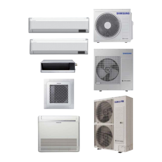
AIR CONDITIONER
MULTI AIR CONDITIONER
INDOOR UNIT
AR07/09/12/15/18/24TSFABWKN
AR07/09/12/15/18/24BSFCMWKN
AC009/012/018BNNDCH
AC009/012/018BNLDCH
AJ009/012/015/018BNHDCH
AC009/012BN1DCH
AC009/012/015/018BNJDCH
AC012/018/024BNZDCH
CONTENTS
1. Precautions
2. Product Specifications
3. Disassembly and Reassembly
4. Troubleshooting
5. PCB Diagram
6. Wiring Diagram
7. Reference Sheet
OUTDOOR UNIT
AJ020BXJ2CH
AJ024BXJ3CH
AJ036BXJ4CH
AJ048BXJ5CH
AJ020BXS3CH
AJ024BXS4CH
AJ030BXS4CH
AJ036BXS4CH
Advertisement
Table of Contents

Related Manuals for Samsung AR07TSFABWKN


Summary of Contents for Samsung AR07TSFABWKN
- Page 1 MULTI AIR CONDITIONER INDOOR UNIT OUTDOOR UNIT AR07/09/12/15/18/24TSFABWKN AJ020BXJ2CH AR07/09/12/15/18/24BSFCMWKN AJ024BXJ3CH AC009/012/018BNNDCH AJ036BXJ4CH AC009/012/018BNLDCH AJ048BXJ5CH AJ009/012/015/018BNHDCH AJ020BXS3CH AC009/012BN1DCH AJ024BXS4CH AC009/012/015/018BNJDCH AJ030BXS4CH AC012/018/024BNZDCH AJ036BXS4CH AIR CONDITIONER CONTENTS 1. Precautions 2. Product Specifications 3. Disassembly and Reassembly 4. Troubleshooting 5. PCB Diagram 6.
-
Page 2: Table Of Contents
Contents 1. Precautions···································································································································1-1 1-1 Precautions for the Service ....................1-1 1-2 Precautions for the Static Electricity and PL...............1-1 1-3 During operation ........................1-2 1-4 Disposing of the unit ......................1-2 1-5 Precautions for the Pump Down ..................1-2 1-6 Others ............................. 1-2 2. - Page 3 Contents 4-5 Setting to Cool or Heat only mode, checking and Cool/Heat modes operation test 4-39 4-6 Fault Diagnosis by Symptom ....................4-41 4-6-1 Indoor.......................... 4-41 4-6-2 Outdoor unit is not powered on – Initial diagnosis ..........4-45 4-6-3 Checking Outdoor Controller ................. 4-46 4-6-4 Outdoor unit fan error....................
-
Page 4: Precautions
>3mm. • Do not extend an electric cord to the air conditioner. No Tapping and No Extension Cords • The air conditioner must be plugged in after you complete the installation. Samsung Electronics... -
Page 5: During Operation
• Current is measured according to ISO standard for energy efficiency. • For servicing the units containing flammable refrigerants, safety checks are required to minimise the risk of ignition. • Servicing shall be performed following the controlled procedure to minimize the risk of flammable refrigerant or gases. Samsung Electronics... -
Page 6: Product Specifications
■ Universal Connection Multi Inverter(Free Joint Multi) Series delivers comfort to 2~5 rooms with a Single Outdoor Unit. Free Joint Multi added Universal indoor units, which can be universally connected to other Samsung outdoor units, to all lineup. ■ Various Indoor units & combinations ·... - Page 7 When you want to operate all indoor units with the cooling mode or heating mode. ■ Wi-Fi Fuction (SmartThings app) SmartThings app is the easy way to turn your home into a smart home. Control the FJM with only one application. This feature is optional to the several models. Samsung Electronics...
-
Page 8: Product Specifications
Product Specifications 2-2 Product Specifications 2-2-1 Indoor Unit Type Wall-mounted Wind-Free QF2 GEO Model AR07TSFABWKN AR09TSFABWKN AR12TSFABWKN AR15TSFABWKN Cooling 2.05 2.64 3.52 4.40 Heating 2.20 3.22 3.52 5.28 Capacity Cooling 7,000 9,000 12,000 15,000 Performance Btu/h Heating 7,500 11,000 12,000... - Page 9 Cross flow fan Cross flow fan Type BLDC BLDC BLDC Part Fan Motor Code DB31-00636A DB31-00636A DB31-00636A Row, Heat Exchanger 2Rx16S + 1Rx8S 2Rx16S 2Rx16S Step Refrigerant Control Device EEV NOT INCLUDED EEV NOT INCLUDED EEV NOT INCLUDED Samsung Electronics...
- Page 10 9.52 Type Turbo Fan Turbo Fan Turbo Fan Type BLDC BLDC BLDC Part Fan Motor Code DB31-00578C DB31-00578C DB31-00578C Row, Heat Exchanger 2Rx8S 2Rx8S 2Rx8S Step Refrigerant Control Device EEV NOT INCLUDED EEV NOT INCLUDED EEV NOT INCLUDED Samsung Electronics...
- Page 11 Cross Flow FAN Type BLDC BLDC BLDC BLDC Part Fan Motor Code DB31-00639B DB31-00639B DB31-00639B DB31-00639B Row, Heat Exchanger 3Rx16S 3Rx16S 3Rx16S 3Rx16S Step Refrigerant Control Device EEV NOT INCLUDED EEV NOT INCLUDED EEV NOT INCLUDED EEV NOT INCLUDED Samsung Electronics...
- Page 12 15.88 Type Sirroco FAN Sirroco FAN Sirroco FAN Type BLDC BLDC BLDC Part Fan Motor Code DB81-05891A DB81-04294H DB81-04294J Row, Heat Exchanger 2Rx24S 3Rx24S 3Rx24S Step Refrigerant Control Device EEV NOT INCLUDED EEV NOT INCLUDED EEV NOT INCLUDED Samsung Electronics...
-
Page 13: Outdoor Unit
10.01 10.01 Part Type BLDC BLDC BLDC BLDC Fan Motor Code DB31-00579A DB31-00579A DB31-00579A DB31-00579A Row, Heat Exchanger 2R*36S 2R*36S 2R*46S 2R*56S Step Refrigerant Control Device Type R-410A R-410A R-410A R-410A Refrigerant Factory Charging 2200 2650 3100 3800 Samsung Electronics... - Page 14 9.171 10.01 Part Type BLDC BLDC BLDC BLDC Fan Motor Code DB31-00579A DB31-00579A DB31-00579A DB31-00579A Row, Heat Exchanger 2R*46S 2R*46S 2R*46S 2R*56S Step Refrigerant Control Device Type R-410A R-410A R-410A R-410A Refrigerant Factory Charging 3400 3400 3400 3600 Samsung Electronics...
-
Page 15: The Comparative Specifications Of Product
Type Design Model Name Net Size Net Weight Sound [W*H*D,mm] [kg] Pressure AJ020BXJ2CH 53.0 880*798*310 AJ024BXJ3CH 57.0 AJ036BXJ4CH 940*998*330 76.5 Normal AJ048BXJ5CH 940*1210*330 87.5 Outdoor AJ020BXS3CH 77.5 AJ024BXS4CH 78.5 940*998*330 AJ030BXS4CH 78.5 Max Heat AJ036BXS4CH 940*1210*330 87.5 2-10 Samsung Electronics... - Page 16 10.6 AR18/24BSFCMWKN 1055*299*215 11.5 41/45 AC009/012BN1DCH 970*135*410 10.0 32/35 Cassette AC009/012/018BNNDCH 575*250*575 11.5 31/34/39 AC009/12BNLDCH 900*199*440 18.9 33/34 Indoor AC018BNLDCH 1100*199*440 22.0 Duct AJ009/012/015/018BNHDCH 850*250*700 26.5 30/31/33/34 Console AC009/012/015/018BNJDCH 720*620*199 15.7 35/38/42/43 MPAH AC012/018/024BNZDCH 445*1092*533 44.5 38/40/43 Samsung Electronics 2-11...
-
Page 17: Combination Table (Outdoor-Indoor)
● ● ● ● ● ● AC018BNLDCH ● ● ● ● ● ● AJ009/012BNHDCH 9/12 ● ● ● ● ● ● ● AJ015BNHDCH ● ● ● ● ● ● ● AJ018BNHDCH ● ● ● ● ● ● 2-12 Samsung Electronics... - Page 18 ≤ 1.0 AJ048BXJ5CH Enabled Enabled Enabled ≤ 1.0 AJ020BXS3CH Enabled Enabled ≤ 1.0 AJ024BXS4CH Enabled Enabled ≤ 1.0 AJ030BXS4CH Enabled Enabled ≤ 1.0 AJ036BXS4CH Enabled Enabled ≤ 1.0 *Mixed installation means the case of mixing AJ***BNHDCH and AC***BNZDCH. Samsung Electronics 2-13...
-
Page 19: Accessory And Option Specifications
Item Description Code No. Remark AC009BN1DCH AC012BN1DCH DB69-01947A,B PAD INSTALL DB69-03017C,D SEAL-DRAIN ASSY DB62-05810A HOSE DRAIN-JOINT DB94-01258C GROMMET-HANGER DB63-00237A MANUAL USERS DB68-11305A Indoor Unit MANUAL INSTALL DB68-11272A INSULATION-BASE DB72-00401C CABLE TIE DB65-10088C CARD WARRANTY 6801-002246 BRACKET-BUSHING DB61-04340A 2-14 Samsung Electronics... - Page 20 ■ AC***BNNDCH Item Description Code No. Q’ty Remark ASSY DRAIN-HOSE DB94-03287A CABLE TIE DB65-10088C SEAL-DRAIN ASSY DB62-11028A Essential Offer SEAL-DRAIN ASSY DB62-11028H (Indoor Unit) SEAL-DRAIN ASSY DB62-11028J MANUAL USERS DB68-11208A MANUAL INSTALL DB68-11209A CARD WARRANTY 6801-002246 BRACKET-CONDUIT DB61-05788A Samsung Electronics 2-15...
- Page 21 MANUAL USERS AJ***BNHDCH : DB68-11295A AC***BNLDCH : DB68-11207A MANUAL INSTALL AJ***BNHDCH : DB68-11296A INSULATION-COVER BAND DB62-04318S INSULATION-HOSE DB62-11028M INSULATION-HOSE D DB62-11028E Indoor Unit ASSY DRAIN HOSE DB62-11028F INSULATION-TUBE OUT DB94-06964B GROMMET-HANGER DB63-00237A CARD WARRANTY 6801-002246 CABLE TIE 6501-001110 2-16 Samsung Electronics...
- Page 22 Description Code No. Q’ty Remark ASSY WIRELESS REMOCON DB96-24901P BATTERY-MN 4301-000121 MANUAL USERS DB68-11212A Essential Offer (Indoor Unit) MANUAL INSTALL DB68-11213A HOLDER-REMOCON DB61-06087A SCREW-TAPPING(M4*L12) 6002-000213 CARD WARRNATY 6801-002246 SEAL-INSTALL OUTLET B62-05580V SEAL-PIPE SVC DB62-05691C CABLE TIE DB65-10088C Samsung Electronics 2-17...
- Page 23 Product Specifications ■ AC***BNZDCH Item Description Code No. Q’ty Remark CARD WARRANTY 6801-002246 Indoor Unit MANUAL INSTALL 2-18 Samsung Electronics...
-
Page 24: Outdoor Unit Accessories
DB68-11298A (AJ036BXJ4CH, AJ048BXJ5CH, AJ***BXS*CH) (AJ020BXJ2CH) Nipple Connector DB67-00789A 12.7mm → 9.52mm (AJ024BXJ3CH) (AJ020BXJ2CH) Flare Nuts DB60-30010B 12.7mm → 9.52mm (AJ024BXJ3CH) (AJ***BX*4CH) DB96-16155A 12.7mm → 9.52mm (AJ***BX*5CH) Ass'y Tube Connector (AJ020BXS3CH, DB96-16155B 12.7mm → 15.88mm AJ***BX*4CH, AJ***BX*5CH) ※ The design and shape can be changed according to the model. Samsung Electronics 2-19... -
Page 25: Disassembly And Reassembly
Disassembly and Reassembly 3. Disassembly and Reassembly ■ Necessary Tools Item Remark +Screw driver Monkey spanner Samsung Electronics... -
Page 26: Outdoor Unit
2) Loosen each 9 screws(CCW) on Cabi-Top. (Use +Screw Driver). 3) Loosen 2 screws(CCW) fixed to assemble Plate Control Out with Cabinet-Side RH. (Use +Screw Driver.) 4) Loosen 10 fixing screws(CCW) on Cabinet- Side RH. (Use +Screw Driver.) Samsung Electronics... - Page 27 (Use +Screw Driver.) Ass’y 1) Detach the Motor Wire from the PCB of Control Out Ass'y Control Out. 2) Detach comp wire and pressure switch- wire from the PCB of A’ssy Control Out. 3) Detach 2 Connect Wires from Reactor. Samsung Electronics...
- Page 28 4) Detach the Heat Exchanger. Befor you disassemble the pipes and Condensor, be sure that there should be no refrgerant remained in the unit. 5) Loosen 3 nuts of the Compressor. (Use Monkey Spanner.) 6) Detach the Compressor. Samsung Electronics...
-
Page 29: Aj036Bxj4Ch, Aj020Bxs3Ch, Aj024Bxs4Ch, Aj030Bxs4Ch
1) Loosen 6 fixing screws (CCW) on the Cabinet-Side RH. (Use +Screw Driver). Cabi Front RH 1) Loosen 3 fixing screws (CCW) on the Cabinet-Front RH. (Use +Screw Driver). Cabi Top 1) Loosen 7 or 9 fixing screws (CCW) on the Cabi-Top. (Use +Screw Driver). Samsung Electronics... - Page 30 Gurad Cond. (Use +Screw Driver). Cabi Back RH 1) Detach the Sensor from the Cabi-Back 2) Loosen 5 fixing screws (CCW) on Cabi- Back RH. (Use +Screw Driver). 3) Pull the hook of Cabi Back RH from the Bracket Valve. Samsung Electronics...
- Page 31 Parts Procedure Remark Plate Case Control 1) Loosen 2 fixing screws (CCW) on the Plate Support Case Control Support. (Use +Screw Driver). Cabi Front LF 1) Loosen 10 fixing screws (CCW) on the Cabinet-Front LF. (Use +Screw Driver). Samsung Electronics...
- Page 32 1) Detach the Motor Wire from PCB of A’ssy Control Out. 2) Loosen 4 fixing bolts (CCW) and detach the Motor. (Use +Screw Driver.) Backet Motor 1) Loosen 2 fixing screws (CCW) and detach the Bracket Motor. (Use +Screw Driver.) Samsung Electronics...
- Page 33 Disassembly and Reassembly Parts Procedure Remark Control Out 1) Detach Comp-Wire and Pressure-Wire from PCB of A’ssy Control Out. 2) Loosen 4 fixing screws (CCW) and detach the Bracket Motor. (Use +Screw Driver.) 3) Separate A’ssy Control Out. Samsung Electronics...
- Page 34 1) Disassemble the pipes in both inlet and outlet with welding torch. 2) Loosen 2 fixing screws (CCW) and detach the Bracket Valve. (Use +Screw Driver.) Compressor 1) Loosen fixing nut (CCW) on the Cover- Terminal. (Use Monkey Spanner or adjust- able Wrench.) 3-10 Samsung Electronics...
- Page 35 When assembling Comp Wire, make sure to match the color and location of the wire with the picture. Heat Exchanger 1) Loosen 2 fixing screws(CCW) on both sides. And loosen 1 fixed screws(CCW) Partition with base.(Use +Screw Driver.) Samsung Electronics 3-11...
-
Page 36: Aj048Bxj5Ch, Aj036Bxs4Ch
2) Remove the 4 screws from the Cabinet Front RH and separate it. (Use + Screw Driver) Cabinet Top 1) Remove the 8 screws which is fixed to each side of cabinet top and separate it. (Use + Screw Driver) 3-12 Samsung Electronics... - Page 37 Cabinet Back RH 1) Pull out the sensor from the cabinet back RH and separate it. 2) Remove the 4 screws which is fixed to each side cabinet back RH and separate it. (Use + Screw Driver) Samsung Electronics 3-13...
- Page 38 Plate Control 1) Remove the 1 screw from the Plate Conrtol and separate it. (Use + Screw Driver) Cabinet Front LH 1) Remove the 10 screws from the canbinet Front LF and separate it. (Use + Screw Driver) 3-14 Samsung Electronics...
- Page 39 Disassembly and Reassembly Parts Procedure Remark Cabinet Front LH 1) Remove the 2 fixing nuts like the picture on the right side. (Use Hexagon Wrench, Monkey Spanner, Hexagon Socket) Samsung Electronics 3-15...
- Page 40 Motor. ( Use + Screw Driver ) 3) Separate the Motor Wire connector from the Outdoor Unit Control Part. Bracket Motor 1) Remove the 2 screws from the Bracket Motor and separate it. (Use + Screw Driver) 3-16 Samsung Electronics...
-
Page 41: Troubleshooting
Error due to connecting outdoor units that do not support the WindFree function : On : Flickering x: Off • If you turn off the air conditioner when the LED is flickering, the LED is also turned off. Samsung Electronics... - Page 42 Outdoor valve clogging error Miss matching error between indoor unit and outdoor unit : On : Flickering x: Off • If you turn off the air conditioner when the LED is flickering, the LED is also turned off. Samsung Electronics...
- Page 43 (Communication error for more than 2 minutes) : On : Flickering x: Off • If you turn off the air conditioner when the LED is flickering, the LED is also turned off. Samsung Electronics...
- Page 44 2 minutes) : On : Flickering x: Off • If you turn off the air conditioner when the LED is flickering, the LED is also turned off. Samsung Electronics...
- Page 45 Error of communication down between the indoor unit and wired remote controller after 3minutes. Error of communication down between the indoor unit and wired Wired remote controller error remote controller after completion of 10 times tracking. COM1/COM2 Cross-installed error Samsung Electronics...
-
Page 46: Outdoor Unit
ERROR ON PIPE IN-C TEMPERATURE SENSOR(SHORT OR OPEN) E333 ERROR ON PIPE IN-D TEMPERATURE SENSOR(SHORT OR OPEN) E334 ERROR ON PIPE IN-E TEMPERATURE SENSOR(SHORT OR OPEN) E335 ERROR ON PIPE OUT-A TEMPERATURE SENSOR(SHORT OR OPEN) E336 ERROR ON PIPE OUT-B TEMPERATURE SENSOR(SHORT OR OPEN) Samsung Electronics... - Page 47 ERROR DUE TO INPUT CURRENT SENSOR OF INVERTER PBA(SHORT/OPEN) E488 INCOMING VOLTAGE SENSOR ERROR E500 IPM/PFCM OVERHEAT ERROR E554 THE REFRIGERANT LEAKS COMPLETELY FROM THE OUTDOOR UNIT ERROR DUE TO INDOOR UNIT SOFTWARE VERSION COMBINATION(INCOMPATIBLE INDOOR E563 UNITSOFTWARE ON A SYSTEM) E590 INVERTER EEPROM CHECKSUM ERROR Samsung Electronics...
-
Page 48: Setting An Indoor Unit Address And Installation Option
• At this point it is possible to start the internal units in the desired mode. ※ If " "doesn’t display, the procedure has failed and it is therefore necessary to read ALL the operator’s NOTE manual before repeating the operating described in steps 1-2-3-4. Samsung Electronics... - Page 49 Indication on the display and action to take when an inverter fault is detected. SEG1 SEG2 SEG3 SEG4 Action to take Fault detection is in progress PBA defect: Replace the Manual Check inspection is required Going into Try fault fault detection detection again mode failed Samsung Electronics...
- Page 50 Outdoor temperature EEV2 current step Running current EEV3 current step Target Discharge temperature EEV4 current step Total capacity of the indoor units Fan RPM (H: high, L: low, Blank: off ) Safety Control (just For Service Technician) 4-10 Samsung Electronics...
-
Page 51: Setting Option
High Temp button Fast button Low Temp button Wind-Free button < AC***BN*DCH / AJ***BNHDCH > Mode button High Temp button High Fan button Low Temp button Low Fan button Samsung Electronics 4-11... -
Page 52: The Procedure Of Setting Option
2 Press ❹ button to enter SEG8. Step 5 Press ❶ button to be changed to FAN mode in the ON status. 1 Press ❺ button to enter SEG9 value. 2 Press ❹ button to enter SEG10 value. 4-12 Samsung Electronics... - Page 53 1 Press ❺ button to enter SEG23 value. 2 Press ❹ button to enter SEG24 value. Step 12 Press ❶ button to check whether the option code you entered is correct or not. Press operation button to enter option. Samsung Electronics 4-13...
-
Page 54: Setting An Indoor Unit Address (Main/Rmc)
• If you set the SEG 9 as 0, the indoor unit will maintain previous RMC ADDRESS even if you input the option value of SEG11~12. 5 The MAIN address is for commnication between the indoor unit and the outdoor unit. Therefore, you must set it to operate the air conditioner properly 4-14 Samsung Electronics... -
Page 55: Setting An Indoor Unit Installation Option
Reserved Indication Disuse and Details Disuse Option SEG7 SEG8 SEG9 SEG10 SEG11 SEG12 Explanation Page Use of drain pump (*1) Indication Details Indication Details Reserved Reserved Reserved Reserved Indication Disuse and Details External drain pump signal use Samsung Electronics 4-15... - Page 56 (*1) If external drain pump signal is used, external control (SEG14) can't be used. (*2) The window on/off function applies to the following unit ‐ AR********** (*3) If you input a number other than 0~4 of the individual control of the indoor unit(SEG20), the indoor is set as "indoor 1". 4-16 Samsung Electronics...
- Page 57 Disuse Use(Heating) Use(Heating) Disuse Use(Cooling) Indication Use(Cooling) Reserved Disuse details (Cooling/Heating) (Cooling/Heating) Use (Cooling Ultra compensation Disuse low speed) Use (Cooling Ultra low speed) Use (Heating/ Disuse Cooling Ultra low speed)) Use (Heating/ Cooling Ultra low speed) Samsung Electronics 4-17...
- Page 58 If you set the Individual control with remote control option to a value other than 0 to 4, it is automatically set to 0 (Indoor 1) • 6) SEG21 Default value of Heating setting compensation is 9°F(5℃). 4-18 Samsung Electronics...
- Page 59 Disuse Use(Heating) Use(Heating) Disuse Use(Cooling) Indication Use(Cooling) Reserved Disuse details (Cooling/Heating) (Cooling/Heating) Use (Cooling Ultra Disuse High ceiling low speed) mode Use (Cooling Ultra low speed) Use (Cooling Ultra Disuse low speed) Use (Cooling Ultra low speed) Samsung Electronics 4-19...
- Page 60 Thermo on Use of buzzer hours Disuse Main, On/Off Existing control Reserved Window Indication On/Off and details Disuse Sub, On/Off Reverse control Window Operation Disuse of 2000 On/Off buzzer hours Disuse Main, On/Off Reverse control Window On/Off 4-20 Samsung Electronics...
- Page 61 Soft Off: The indoor unit turns off its operation at the indicated time in the table for Installation Option after its final motion detection. But, it turns on again if the MDS detects motion. Hard Off: Designated time after SOFT OFF, it cannot turn on automatically when it detects motion. Users should control to turn on the indoor unit with remote control, etc. Samsung Electronics 4-21...
- Page 62 Details 2.7°F(1.5°C) 10 minutes 2.7°F(1.5°C) 20 minutes 5.4°F(3°C) No delay 5.4°F(3°C) 10 minutes 5.4°F(3°C) 20 minutes 8.1°F(4.5°C) No delay 8.1°F(4.5°C) 10 minutes 8.1°F(4.5°C) 20 minutes (Heater time 10.8°F(6°C) No delay delay) 10.8°F(6°C) 10 minutes 10.8°F(6°C) 20 minutes 4-22 Samsung Electronics...
- Page 63 If you set the Individual control with remote control option to a value other than 0 to 4, it is automatically set to 0 (Indoor 1) • 4) SEG21 Default value of Heating setting compensation is 3.6°F(2℃). Samsung Electronics 4-23...
- Page 64 Use (Cooling Ultra low Disuse speed) Use (Cooling Ultra low speed) Use (Heating/Cooling Disuse Ultra low speed) Use (Heating/Cooling Ultra low speed) Option SEG7 SEG8 SEG9 SEG10 SEG11 SEG12 Function Page Indication Indication Details Reserved Reserved Reserved Reserved Reserved details 4-24 Samsung Electronics...
- Page 65 If you set the Individual control with remote control option to a value other than 0 to 4, it is automatically set to 0 (Indoor 1) • 4) SEG21 Default value of Heating setting compensation is 9°F(5°C). Samsung Electronics 4-25...
- Page 66 Disuse Use(Heating) Use(Heating) Disuse Use(Cooling) Reserved Reserved Indication Use(Cooling) Disuse Use (Cooling/Heating) details Use (Cooling/Heating) Use (Cooling Ultra low Disuse speed) Use (Cooling Ultra low speed) Use (Heating/Cooling Disuse Ultra low speed) Use (Heating/Cooling Ultra low speed) 4-26 Samsung Electronics...
- Page 67 2.7°F(1.5°C) No delay 2.7°F(1.5°C) minutes Indication 2.7°F(1.5°C) details minutes 5.4°F(3°C) No delay 5.4°F(3°C) minutes 5.4°F(3°C) minutes 8.1°F(4.5°C) No delay 8.1°F(4.5°C) minutes external Master drain pump 8.1°F(4.5°C) minutes (Heater 10.8°F(6°C) No delay time delay) 10.8°F(6°C) minutes 10.8°F(6°C) minutes Samsung Electronics 4-27...
- Page 68 If you set the Individual control with remote control option to a value other than 0 to 4, it is automatically set to 0 (Indoor 1) • 4) SEG21 Default value of Heating setting compensation is 3.6°F(2℃). 4-28 Samsung Electronics...
-
Page 69: Changing The Addresses And Option Individually
CAUTION If you set an indoor unit as the master indoor unit by using the remote control, the outdoor unit automatically operate in the current mode of the master indoor unit. Samsung Electronics 4-29... -
Page 70: Changing A Particular Option
AC012BN1DCH SEG1~6 0173FC 0173FC SEG7~12 1930F8 19344D SEG13~18 271A23 272328 SEG19~24 371120 371120 SEG25~30 020010 020010 SEG31~36 100031 100051 SEG37~42 200000 200000 SEG43~48 300000 300000 SEG49~54 030000 030000 SEG55~60 100000 100000 SEG61~66 200000 200000 SEG67~72 300002 300002 4-30 Samsung Electronics... - Page 71 SEG55~60 100000 100000 100000 SEG61~66 200000 200000 200000 SEG67~72 300002 300002 300002 0.3≤P≤1.5 mmAq 01C3FC-1C5407-271A23-370000 01C3FC-1C54BC-272328-370000 01C3FC-1C54FB-23343C-370000 1.5≤P≤2.6 mmAq 01C3FC-1C546B-271A23-370000 01C3FC-1C55F0-272328-370000 01C3FC-1C583D-23343C-370000 2.6≤P≤4.0 mmAq 01C3FC-1C55C0-271A23-370000 01C3FC-1C5944-272328-370000 01C3FC-1C5980-23343C-370000 4.0≤P≤5.0 mmAq 01C3FC-1C5903-271A23-370000 01C3FC-1C5986-272328-370000 01C3FC-1C59B2-23343C-370000 5.0≤P≤6.0 mmAq 01C3FC-1C5945-271A23-370000 01C3FC-1C59B9-272328-370000 01C3FC-1C59F5-23343C-370000 Samsung Electronics 4-31...
- Page 72 020010 020010 SEG31~36 100000 100000 100000 100000 SEG37~42 200000 200000 200000 200000 SEG43~48 300000 300000 300000 300000 SEG49~54 030000 030000 030000 030000 SEG55~60 100000 100000 100000 100000 SEG61~66 200000 200000 200000 200000 SEG67~72 300002 300002 300002 300002 4-32 Samsung Electronics...
- Page 73 27484F SEG19~24 370000 370000 370000 SEG25~30 020010 020010 020010 SEG31~36 100000 100000 100000 SEG37~42 200000 200000 200000 SEG43~48 300000 300000 300000 SEG49~54 030000 030000 030000 SEG55~60 100000 100000 100000 SEG61~66 200000 200000 200000 SEG67~72 300002 300002 300002 Samsung Electronics 4-33...
-
Page 74: Items To Be Checked First
The compressor stops intermittently or the fan speed of the COOL mode or DRY mode, and fan speed of the indoor unit decreases to prevent inside/outside air frozen indoor unit decreases. depending on the inside/outside air temperature. 4-34 Samsung Electronics 4-34... - Page 75 Troubleshooting ■ If Error code is displayed on indoor or outdoor LED, check as follows; Contents Turn on the system. But outdoor units PCB displayed E201 or E101 Error code. Check point Remarks Check point Remarks Check to power cable to indoor units. Step 1 Wire connect Check to communication cable indoor units.
- Page 76 Troubleshooting - Address setting another case Contents When the system installation is finished, outdoor unit’s PCB display E202 Error code. Check point Remarks This problem is caused by outdoor unit’s communica- Analysis tion part trouble or indoor units power and communica- The pipe checking operation tion line trouble.
- Page 77 Troubleshooting - Operation Error Contents While using cooling or heating, indoor units display E161 Error code. Check point Remarks This problem is caused by user’s fault. User’s simultaneously operate 2 more indoor units in the same time cool- Analysis ing and heating mode. FJM is operate by just cooling or heating mode only.
- Page 78 Troubleshooting Contents While using heating, outdoor unit turn off and display E404 Error code. Check point Remarks Heating overload safety mode make this situation. Analysis After System restart automatically until 3 times, System display this error code and stop. System can operate by remote controller input signal or K3(reset) key input. Step 1 Check indoor units air flow.
-
Page 79: Setting To Cool Or Heat Only Mode, Checking And Cool/Heat Modes Operation Test
Troubleshooting 4-5 Setting to Cool or Heat only mode, checking and Cool/Heat modes operation test Setting the outdoor option • Press and hold K2 to enter the option setting. (Only available when the operation is stopped) - If you enter the option setting, display will show the following. - Seg 1 and Seg 2 will display the number for selected option. - Page 80 This function enables the indoor units connected to the outdoor unit to operate in a specific mode. You can set each mode with Keys on the Main PCB in the outdoor unit. Set mode SEG1 SEG2 SEG3 SEG4 Cooling and Heating Only Cooling Only Heating • Default value: Cooling and Heating mode 4-40 Samsung Electronics...
-
Page 81: Fault Diagnosis By Symptom
In this case, is the resistance 8.300 value out of range in the temperature 10.00 table on the right? 12.10 Indoor temperature sensor 14.70 failure (replace) 18.00 Restart the system after 22.00 replacing the PCB 28.30 33.90 42.30 Samsung Electronics 4-41... - Page 82 PCB? Connect the connector to PCB and restart the unit. Is there foreign substance stuck in the motor fan? Remove the foreign substance and restart the unit. Replace the PCB and restart the unit. 4-42 Samsung Electronics...
- Page 83 PCB and replace the PCB Reconnect the cable connecting the outdoor unit to the indoor unit and restart the unit. If the communication still doesn’t work, replace the indoor unit PCB. Good +0.7V -0.7V Samsung Electronics 4-43...
- Page 84 EEPROM component failure, EEPROM circuit parts missing/damaged/soldering failure. Are the EEPROM circuit components in good conditions? (missing components / damage / soldering failure) Replace the PCB if the restart fails Restart the unit after replacing the PCB 4-44 Samsung Electronics...
-
Page 85: Outdoor Unit Is Not Powered On - Initial Diagnosis
2 (~) and 4 (~) of the bridge diode 220V? Is the fuse connected? Replace the fuse Replace the inverter PBA Is the resistance value of R001 200Ω? Is the reactor connector Connect the reactor. connected correctly? Replace the PBA. Samsung Electronics 4-45... -
Page 86: Checking Outdoor Controller
Main control 5V CE159 Voltage 4.75V - 5.25V 4. Checking PFCM Check Resistance between R and S AJ020BXJ2CH, AJ024BXJ3CH AJ020BXS3CH, AJ***BX*4CH, AJ***BX*5CH (INVERTER PBA) PFCM PFCM Measuring point Normal value Resistance R - S over the hundreds ㏀ 4-46 Samsung Electronics... -
Page 87: Outdoor Unit Fan Error
1V~6V? Replace inverter PCB. Is the fan running the operation mode? Does the voltage between pin6 and pin3 of the fan (CNP901 or CN901) Replace the fan motor. fluctuate? (High 5V~6V, Low:0V~1V) Replace the inverter PCB. Samsung Electronics 4-47... -
Page 88: Compressor Startup Error, Compressor Lock Error, Compressor Rotation Error
Is the resistance value Replace the compressor. between the compressor boday and the chassis in the range of Mega Ω Is the compressor connection wire connected to the Check the connection wire. compressor correctly? Replace the outdoor unit Main PCB. 4-48 Samsung Electronics... -
Page 89: Ipm Over Current Error
Trun off the power and reconnect the table. value normal? Does the voltage Trun off the power and correct or replace between pin6 and pin3 of the fan (CN901) fluctuate? the temperature sensor location. (High 5V~6V, Low:0V~1V) Replace the inverter PCB. Samsung Electronics 4-49... -
Page 90: Checking Temperature Sensor
40°C - 115kohm Connect the sensor to PBA connector supply power and measure the voltage of sensor in the connector. Exchange the Outdoor PBA. Below 0.5V or Over 4.5V? Micom error or connector check. Exchange the Outdoor PBA. 4-50 Samsung Electronics... - Page 91 40°C - 5.83kohm Connect the sensor to PBA connector supply power and measure the voltage of sensor in the connector. Below 0.5V or Over 4.5V? Exchange the Outdoor PBA. Micom error or connector check. Exchange the Outdoor PBA. Samsung Electronics 4-51...
-
Page 92: Pcb Inspection
The parts should be replaced in the following procedure. The repair is completed. Check the operation of the new part. Replace it with a new part. Detach the faulty part. Check for any faulty part. Set an address. 4-52 Samsung Electronics... -
Page 93: Pcb Diagram
PCB Diagram 5. PCB Diagram 5-1 Indoor unit ■ Slim 1 Way, Mini 4Way ▶ This Document can not be used without Samsung’s authorization. Samsung Electronics... - Page 94 #1 : COM1(F1) #1 : L- LIVE POWER INPUT #1 : N-NEUTRAL POWER #2 : COM1(F2) OUTPUT #3 : V1(DC12V) #4 : V2(GND) #5 : COM2(F3) #6 : COM2(F4) This Document can not be used without Samsung’s authorization. Samsung Electronics...
- Page 95 PCB Diagram ■ Slim 1Way (PANEL) ▶ This Document can not be used without Samsung’s authorization. ① CN401-DISPLAY #1: DC12V #2: LED_0 #3: LED_1 #4: LED_2 #5: LED_3 #6: LED_4 #7: - #8: REMOCON Signal Out #9 : PANEL SELECTION...
- Page 96 PCB Diagram 1. CN101-DISPLAY #1 : 12V #2~6 : LED CONTROL SIGNAL This Document can not be used without Samsung’s authorization.
- Page 97 #1: DC12V #2: LED_0 #3: LED_1 #4: LED_2 #5: LED_3 #6: LED_4 #7: - #8: REMOCON OUTPUT SIGNAL #9 : PANEL SELECTION #10: REMOCON INPUT SIGNAL #11: GND #12: DC5V #13: - This Document can not be used without Samsung’s authorization.
- Page 98 PCB Diagram ■ Mini 4Way (PANEL) - This Document can not be used without Samsung’s authorization. 1. CN01-DISPLAY #1 : DC12V #2 : LED_Operation #3 : LED_Defrost #4 : LED_Timer #5 : - #6 : LED_Filter #7 : - #8 : Remocon Signal Out...
- Page 99 PCB Diagram ■ Home Duct ▶ This Document can not be used without Samsung’s authorization. Samsung Electronics...
- Page 100 #3~6 : FAN MOTOR SIGNAL CONTROL SIGNAL SIGNAL CONTROL SIGNAL #6 : DC 5V #3 : DC 12V #7~12 : COMMUNICATION #4 : GND SIGNAL #4~6 : COM2 COMMUNICATION SIGNAL This Document can not be used without Samsung’s authorization. Samsung Electronics...
- Page 101 PCB Diagram ■ Duct S ▶ This Document can not be used without Samsung’s authorization. Samsung Electronics...
- Page 102 #5 : DISCHARGE SENSOR #6 : GND 17. CN826-FAN MOTOR 18. SH100-EARTH #1 : MOTOR-U PHASE #1 : GND EARTH #2 : MOTOR-V PHASE #3 : MOTOR-W PHASE This Document can not be used without Samsung’s authorization. 5-10 Samsung Electronics...
- Page 103 PCB Diagram ■ Console ▶ This Document can not be used without Samsung’s authorization. 11 16 19 18 14 4 13 5 12 15 6 Samsung Electronics 5-11...
- Page 104 17. CN808-EEV 18. CN301-DOWNLOAD 19. CN201-EEPROM PBA CONNECTOR #1~#4:EEV CONTROL SIGNAL →For Developer only,Not available in #1:GND #5,#6:DC12V Actual Site #2:NOT USED →20 Pin Down Loader #3~#7:EEPROM SIGNAL This Document can not be used without Samsung’s authorization. 5-12 Samsung Electronics...
-
Page 105: Outdoor Pcb Diagram
PCB Diagram 5-2 Outdoor PCB Diagram ■ AJ020BXJ2CH, AJ024BXJ3CH (INVERTER PBA) ▶ This Document can not be used without Samsung’s authorization. 1. CNP351-MAIN INV 2. CN030-MAIN POWER 3. CN571-ECO DOWNLOAD 4. CNP901-BLDC FAN #1 : RXD #1 : N #1 ~ 4 : ECO DOWNLOAD... - Page 106 PCB Diagram ■ AJ020BXJ2CH, AJ024BXJ3CH (MAIN PBA) ▶ This Document can not be used without Samsung’s authorization. 5-14 Samsung Electronics...
- Page 107 #3 : EEV D SIGNAL #4 : EEV A SIGNAL #4 : EEV B SIGNAL #4 : EEV D SIGNAL #5 : GND #5 : GND #5 : GND This Document can not be used without Samsung’s authorization. Samsung Electronics 5-15...
- Page 108 PCB Diagram ■ AJ020BXS3CH, AJ***BX*4CH, AJ***BX*5CH (INVERTER PBA) ▶ This Document can not be used without Samsung’s authorization. 1. L, N - AC POWER INPUT 2. REACTOR-A1/B1 3. REACTOR-A2/B2 4. CN551 - DOWNLOAD #1 : L - LIVE POWER INPUT /...
- Page 109 PCB Diagram ■ AJ020BXS3CH, AJ***BX*4CH, AJ***BX*5CH (MAIN PBA) ▶ This Document can not be used without Samsung’s authorization. Samsung Electronics 5-17...
- Page 110 #3 : GND #2 : - #4 : COMP CHECK #4 : DC 5V #3 : N - NEUTRAL POWER #5 : DC 12V OUTPUT #6 : INV POWER CTRL This Document can not be used without Samsung’s authorization. 5-18 Samsung Electronics...
- Page 111 PCB Diagram ■ AJ020BXS3CH, AJ***BX*4CH, AJ***BX*5CH (MAIN PBA) - This Document can not be used without Samsung’s authorization. 1. L1 - AC POWER OUTPUT 2. L2 - AC POWER OUTPUT 3. CN01 - AC POWER OUTPUT 4. EARTH #1 : L - RELAY CONTACT...
-
Page 112: Wiring Diagram
6. Wiring Diagram 6-1 Indoor Unit ■ Slim 1Way, Mini 4Way This Document can not be used without Samsung’s authorization. Samsung Electronics... - Page 113 ■ Home Duct This Document can not be used without Samsung’s authorization. Samsung Electronics...
- Page 114 ■ Duct S Samsung Electronics...
- Page 115 ■ Console This Document can not be used without Samsung’s authorization. Samsung Electronics...
- Page 116 ■ MPAH Samsung Electronics...
-
Page 117: Outdoor Unit
F) at 200k Ω ° ° ※OPTION L1 L2 L1 L2 L1 L2 AC POWER INDOOR-UNIT INDOOR-UNIT USE COPPER SUPPLY WIRES. INPUT POWER COMM UTILISER DES FILS D'ALIMENTATION EN CUIVRE. This Document can not be used without Samsung’s authorization. Samsung Electronics... - Page 118 ■ AJ020BXS3CH, AJ***BX*4CH, AJ***BX*5CH This Document can not be used without Samsung’s authorization. Samsung Electronics...
-
Page 119: Preference Sheet
Contact CAUTION your dealer for advice. • Minimum installation height of indoor unit is 0.6 m for floor mounted, 1.8 m for wall, 2.2 m for ceiling. Samsung Electronics... -
Page 120: Outdoor Unit
2. Make sure that you put the remote control unit in an area not exposed to direct sunlight, and where there is no source of heat. 3. Make sure that you use the remote control unit in an area away from TVs, audio units, cordlessphones, fluorescent lighting. Samsung Electronics... -
Page 121: Connecting Up And Purging The Circuit
(N · m) port cap (Refer to the table) ø 6.35 20 to 25 ø 9.52 20 to 25 10 to 12 ø 12.70 25 to 30 R-140A : Diameter of the screw-1/2-20UNF ø 15.88 30 to 35 Samsung Electronics... -
Page 122: Refrigerant Refill
7) Stop operation of the air conditioner. AJ034NCJ5CH, AJ038NCJ5CH 8) Close the 3 way valve, disconnect the pres- sure gauge, and open the 3 way valve again. 9) Close the cap of each valve. Samsung Electronics... -
Page 123: Refrigerant Adjustment
Tightening torque Outer diameter (mm) Body cap (N · m) Charging port cap (N · m) ø 6.35 20 to 25 ø 9.52 20 to 25 10 to 12 ø 12.70 25 to 30 ø 15.88 30 to 35 Samsung Electronics... -
Page 124: Pump Down" Procedure
6. Make sure you do not bend the connection pipes in the middle and store together with the cables. 7. Move the indoor and outdoor units to a new location. 8. Remove the mountin g plate for the indoor unit and move it to a new location. Samsung Electronics... -
Page 125: Index Of Model Name
Tri-care Filter (10) Buyer (3) Year America 2016 Europe 2017 (6) Design 2018 Wind-Free, GEO 2019 Wind-Free, AIRISE 2020 2021 AIRISE 2022 2023 (4) Inverter type (7) Series HP, R410A 1st Model HP, R32 2nd Model Wind-Free Mass Samsung Electronics... - Page 126 220~240V, 50/60Hz 2023 200~220V, 50Hz 208~230V, 60Hz, 3Φ 220~240V, 50Hz 127V, 50Hz (4) Inverter type 208~230V, 60Hz, 3Φ 380~415, 50/60Hz, 3Φ Indoor unit (NASA) 380~415V, 50Hz, 3Φ Outdoor unit (NASA) Indoor unit (Non NASA) Outdoor unit (Non NASA) Samsung Electronics...
- Page 127 2021 200~220V, 50Hz 208~230V, 60Hz, 3Φ 2022 220~240V, 50Hz 127V, 50Hz 2023 208~230V, 60Hz, 3Φ 380~415, 50/60Hz, 3Φ 380~415V, 50Hz, 3Φ (4) Product type Indoor unit (NASA) Outdoor unit (NASA) Indoor unit (Non NASA) Outdoor unit (Non NASA) Samsung Electronics...
-
Page 128: Refrigerating Cycle Diagram
(T_O1) Compressor (Comp) ROOM A Service Valve - Gas Pipe1 (SV_G1) Thermistor - Out 2 (T_O2) ROOM B Service Valve - Gas Pipe2 (SV_G2) Thermistor - Out 3 (T_O3) ROOM C Service Valve - Gas Pipe3 (SV_G3) 7-10 Samsung Electronics... - Page 129 ROOM C Service Valve (AC) - Gas Pipe3 (SV_G3) Thermistor - Out 4 (T_O4) Compressor ROOM D Service Valve (Comp) Thermistor - Out 5 - Gas Pipe3 (SV_G4) (T_O5) ROOM E Service Valve - Gas Pipe3 (SV_G5) Samsung Electronics 7-11...
- Page 130 ROOM B Service Valve Thermistor - Out 3 - Gas Pipe2 (SV_G2) (T_O3) Accmulator ROOM C Service Valve (AC) Thermistor - Out 4 - Gas Pipe3 (SV_G3) (T_O4) Compressor ROOM D Service Valve (Comp) - Gas Pipe3 (SV_G4) 7-12 Samsung Electronics...
- Page 131 ROOM B Service Valve Thermistor - Out 3 - Gas Pipe2 (SV_G2) (T_O3) Accmulator ROOM C Service Valve (AC) Thermistor - Out 4 - Gas Pipe3 (SV_G3) (T_O4) Compressor ROOM D Service Valve (Comp) - Gas Pipe3 (SV_G4) Samsung Electronics 7-13...
-
Page 132: Pressure & Capacity Mark
(Full name : Heat exchanger; A device, used to transfer heat from a fluid on one side of a barrier assemble evaporator / to a fluid on the other side without bringing the fluids into direct contact. assemble condenser) 7-14 Samsung Electronics... -
Page 133: Q & A For Non-Trouble
Samsung Electronics do not manufacture drain pumps. So, we are not able to correct the drain pump problems. Whenever the air conditioner is turned on, it irritates my eyes and gives me a headache. - Page 134 Also, the remote controller may not work under intensive light from a 3-wave length lamp or a neon sign due to the EMI. In this case, take the remote controller closer to the receiver. 7-16 Samsung Electronics...
- Page 135 There is a cost table. But, our service engineer needs to visit to total up the cost correctly. When you move in, make sure to contact Samsung Electronics Service Center or Authorized Service Agent in advance to streamline the process.
-
Page 136: Common Sense Of Refrigeration
But generally the value of fresh indoor temperature is that below 0.2(m/s) of indoor air circulation, the temperature is 21~28°C when the wall temperature is the same as the indoor's and relative humidity is 30~31% in summer, the winter temperature is 20~24°C and relative humidity is 30~60% in winter. 7-18 Samsung Electronics... - Page 137 China china.samsungportal.com © Samsung Electronics Co., Ltd. September. 2021. This Service Manual is a property of Samsung Electronics Co., Ltd. Printed in Korea. Any unauthorized use of Manual can be punished under Code No. AC-00261E_2 applicable International and/or domestic law.
Need help?
Do you have a question about the AR07TSFABWKN and is the answer not in the manual?
Questions and answers
UNIT WILL NOT TURN OFF
The Samsung AR07TSFABWKN unit may not turn off because it is exposed to direct sunlight and hot air cannot escape properly. This can cause the unit to continue operating during hot conditions. Setting up a sun blind and clearing obstacles around the outdoor unit can improve ventilation and prevent this issue. Additionally, cleaning the outdoor unit or spraying water on the heat exchanger during a heat wave can help prevent frequent shut-offs and improve cooling performance.
This answer is automatically generated
Come utilizzare il telecomando
The remote control for the Samsung AR07TSFABWKN communicates with the unit through the "Remocon Input Signal" and "Remocon Output Signal" connections on the PCB. To use the remote control:
1. Ensure the unit is powered with DC5V and properly connected to the remote control input.
2. Point the remote control at the unit and press the desired buttons to send signals.
3. The unit will receive the signal through the "Remocon Input Signal" and process the command.
4. If necessary, check the "Panel Selection" setting to ensure compatibility.
For troubleshooting, verify that the remote control has working batteries and is properly aligned with the receiver.
This answer is automatically generated