Table of Contents
Advertisement
S/M No. : OR6L4B5S001
Service Manual
Microwave Oven
Model: KOR-6L4B5S69
Caution
: In this Manual, some parts can be changed for improving,
their performance without notice in the parts list. So, if you
need the latest parts information, please refer to PPL(Parts
Price List) in Service Information Center (http://svc.dwe.co.kr).
Mar. 2011
Advertisement
Table of Contents

Subscribe to Our Youtube Channel
Related Manuals for Daewoo KOR-6L4B5S69


Summary of Contents for Daewoo KOR-6L4B5S69
- Page 1 S/M No. : OR6L4B5S001 Service Manual Microwave Oven Model: KOR-6L4B5S69 Caution : In this Manual, some parts can be changed for improving, their performance without notice in the parts list. So, if you need the latest parts information, please refer to PPL(Parts Price List) in Service Information Center (http://svc.dwe.co.kr).
-
Page 2: Table Of Contents
PRECAUTIONS TO BE OBSERVED BEFORE AND DURING SERVICING TO AVOID POSSIBLE EXPOSURE TO EXCESSIVE MICROWAVE ENERGY (a) Do not operate or allow the oven to be operated with the door open. (b) Make the following safety checks on all ovens to be serviced before activating the magnetron or other micro- wave source, and make repairs as necessary: (1) Interlock operation, (2) Proper door closing, (3) Seal and sealing surfaces (arcing, wear, and other damage), (4) Damage to or loosening of hinges and latches, (5) Evidence of dropping or abuse. -
Page 3: Exposure To Excessive Microwave Energy
SAFETY AND PRECAUTIONS CAUTION This device is to be Serviced only by Properly Qualified Service Personel. Consult the Service Manual for Proper Service Procedures to Assure Continued Safety Operation and for Precautions to be Taken to Avoid Possible Exposure to Excessive Microwave Energy. 1. -
Page 4: Specifications
SPECIFICATIONS POWER SUPPLY 230V AC, 50Hz SINGLE PHASE WITH GROUNDING INPUT POWER 1200 W MICROWAVE ENERGY OUTPUT 800 W FREQUENCY 2,450MHz OUTSIDE DIMENSIONS (W 446 x 270 x 318 mm CAVITY DIMENSIONS (W 295 x 219 x 303 mm CAVITY VOLUME 20 L NET WEIGHT APPROX. -
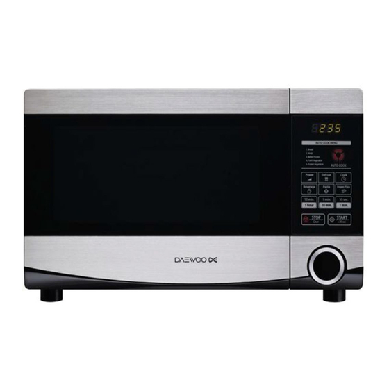
Page 5: External View
EXTERNAL VIEW 1. OUTER DIMENSION... -
Page 6: Features Diagram
2. FEATURES DIAGRAM 1 Door latch - When the door is closed, it will auto- 7 Roller guide - This must always be used for cook- matically shut off. If the door is opened while the ing together with the glass cooking tray. oven is operating, the magnetron will automatically 8 Glass cooking tray - Made of special heat resis- shut off. -
Page 7: Control Panel
3. CONTROL PANEL 1 DISPLAY - Cooking time, power level, indica- 6 ONE TOUCH COOK - Used to cook or reheat tors and the current time are displayed. specific quantities of food. 2 AUTO COOK - Used to cook or reheat many of 7 TIME SET PAD - Used to set the cooking time favorite food. -
Page 8: Installation
• This appliance is supplied with cable of special type, which, if damaged, must be repaired with cable of same type. Such a cable can be purchased from DAEWOO and must be installed by a qualified person. 6. Examine the oven after unpacking for any damage such as: A misaligned door, broken door or a dent in cavity. -
Page 9: Operations And Functions
OPERATIONS AND FUNCTIONS 11. Connect the mains lead to an electrical outlet. 12. After placing the food in a suitable container, open the oven door and put it on the glass tray. The glass tray must always be in place during cooking. 13. -
Page 10: Disassembly And Assembly
DISASSEMBLY AND ASSEMBLY Cautions to be observed when troubleshooting. Unlike many other appliances, the microwave oven is high-voltage, high-current equipment. It is completely safe during normal operation. However, carelessness in servicing the oven can result in an electric shock or possible danger from a short circuit. You are asked to observe the following precautions carefully. - Page 11 1. To remove cabinet 1) Remove four screws on cabinet back. 2) Pull the cabinet backward. 2. To remove door assembly 1) Remove two screws which secure the stopper hinge top. 2) Remove the door assembly from top plate of cavity. 3) Reverse the above for reassembly.
- Page 12 3. To remove door parts. DOOR ASSEMBLY : 3511730150 REF No. PART CODE PART NAME DESCRIPTION Q’TY REMARK 3511730150 DOOR AS KOR-6L455S 3511730170 DOOR SUB AS KOR-6L455S SERVICE 3515204120 STOPPER HINGE *T AS KOR-6L0B1A 3511706130 DOOR PAINTING AS KOR-6L0B1A 3517003700 BARRIER SCREEN *I PE T0.1 3512302700...
- Page 13 4. Method to reduce the gap between the door seal and the oven front surface. (1) To reduce gap located on part ‘A’ • Loosen two screws on the stopper hinge top, and then push the door to contact the door seal to the oven front sur- face.
- Page 14 5. To remove control panel parts. C/PANEL ASSEMBLY : PKCPSWFLV0 REF No. PART CODE PART NAME DESCRIPTION Q’TY REMARK PKCPSWFLV0 CONTROL-PANEL AS KOR-6L4B5S 3518572830 SWITCH MEMBRANE KOR-6L4B5S 3511730140 CONTROL-PANEL SUB AS KOR-6L455S PKMPMSFLH0 PCB MAIN MANUAL AS KOR-6L0B3S 7122401211 SCREW TAPPING T2S TRS 4X12 MFZN 3513702700 LEVER DOOR OPEN...
- Page 15 6. To remove guide wind parts. GUIDE WIND ASSEMBLY : 3512529420 REF No. PART CODE PART NAME DESCRIPTION Q’TY REMARK 3512529420 GUIDE WIND AS KOC-9Q0T7R 3512527600 GUIDE WIND 3963514350 MOTOR SHADED POLE 230V 60Hz MW10CA-M04 7121402511 SCREW TAPPING T2S PAN 4X25 MFZN 3511800300 PP+30%GLASS 3518608700...
- Page 16 7. To remove high voltage capacitor. 1) Remove the screw which secure the grounding ring terminal of the H.V. diode and the capacitor holder. 2) Remove the H.V. diode from the capacitor holder. 3) Reverse the above steps for reassembly. High voltage circuit wiring 8.
- Page 17 9. To remove wind guide assembly. 1) Remove the screw for earthing. 2) Remove the noise filter from the wind guide. 3) Remove the screw which secure the wind guide assembly. 4) Draw forward the wind guide assembly. 5) Pull the fan from the motor shaft. 6) Remove two screws which secure the motor shaded pole.
-
Page 18: Interlock Mechanism And Adjustment
INTERLOCK MECHANISM AND ADJUSTMENT The door lock mechanism is a device which has been specially designed to completely eliminate microwave radiation when the door is opened during operation, and thus to perfectly prevent the danger resulting from the leakage of microwave. Primary interlock switch Hook... -
Page 19: Troubleshooting Guide
TROUBLESHOOTING GUIDE Following the procedure below to check if the oven is defective or not. 1. Check grounding before trouble checking. 2. Be careful of the high voltage circuit. 3. Discharge the high voltage capacitor. 4. When checking the continuity of the switches, fuse or high voltage transformer, disconnect one lead wire from these parts and check continuity with the AC plug removed. - Page 20 CONDITION CHECK RESULT CAUSE REMEDY Replace Defective mag- Outlet has Check continuity of magnetron Continuity netron proper volt- age Fuse does not Replace Defective mag- blow. Check continuity of Continuity netron noise filter board Replace Open power sup- Check continuity of Continuity power supply cord ply cord...
- Page 21 (TROUBLE 3) No microwave oscillation even though fan motor rotates. CONDITION CHECK RESULT CAUSE REMEDY Continuity microwave Check continuity of high oscillation voltage fuse Replace high voltage fuse Continuity Replace Check continuity of high Defective high voltage capacitor terminals voltage trans- with wires removed former Continuity in...
- Page 22 (TROUBLE 4) The following visual conditions indicate a probable defective touch control circuit 1. Incomplete segments, 1) Segments missing. 2) Partical segments missing. 3) Digit flickering other than normal display slight flickering. 4) " :0" does not display when power is on. 2.
-
Page 23: Measurement And Test
MEASUREMENT AND TEST 1. MEASUREMENT OF THE MICROWAVE POWER OUTPUT Microwave output power can be checked by indirectly measuring the temperature rise of a certain amount of water exposed to the microwave as directed below. PROCEDURE 1. A cylindrical container of borosilicate glass is used for the test. It has a maximum thickness of 3mm, an external diameter of approximately 190mm and a height of approximately 90mm. -
Page 24: Microwave Radiation Test
2. MICROWAVE RADIATION TEST CAUTION : 1. Make sure to check the microwave leakage before and after repair of adjustment. 2. Always start measuring of an unknown field to assure safety for operating personnel from microwave energy. 3. Do not place your hands into any suspected microwave radiation field unless the safe density level is known. 4. -
Page 25: Component Test Procedure
3. COMPONENT TEST PROCEDURE • High voltage is present at the high voltage terminal of the high voltage transformer during any cooking cycle. • It is neither necessary nor advisable to attempt measurement of the high voltage. • Before touching any oven components or wiring, always unplug the oven from its power source and discharge the capacitor. -
Page 26: Wiring Diagram
WIRING DIAGRAM... -
Page 27: Printed Circuit Board
PRINTED CIRCUIT BOARD 1. CIRCUIT CHECK PROCEDURE 1. Low Voltage Transformer check • The low voltage transformer is located on the P.C.B. • Measuring condition: input voltage : 230V / Frequency : 50Hz Terminal Voltage LOAD NO LOAD (4,5)-6 or (7,8)-6 AC 14 V AC 17 V NOTE :... - Page 28 Measure Point...
- Page 29 3. When there is no microwave oscillation 1) When touching the START pad, oven lamp does not turn on. Fan motor does not rotate, but cook indicator in display comes on. - Check method POINT STATE RELAY 2 ON 5VDC RELAY 2 OFF 15VDC 2) When touching the START pad, oven lamp turns on.
-
Page 30: Pcb Circuit Diagram
2. PCB CIRCUIT DIAGRAM... -
Page 31: Location No
3. PCB LOCATION NO. NAME SYMBOL SPECIFICATION PART CODE Q’TY BUZZER BM-20K 3515600100 CAPACITOR CERAMIC C1,2,3,8,9 50V 0.1UF Z AXIAL CCZF1H104Z CAPACITOR CERAMIC C4,5,6,7 50V 1000PF Z AXIAL CCZB1H102K CAPACITOR ELECTRO 50V RS 10UF(5X11) CEXE1H100A CAPACITOR ELECTRO 50V RSS 220UF(10X16) CEXF1H221V CAPACITOR ELECTRO 25V RSS 1000UF(13X20) -
Page 32: Exploded View And Parts List
EXPLODED VIEW AND PARTS LIST 1. DOOR ASSEMBLY Refer to Disassembly and assembly. 2. CONTROL PANEL ASSEMBLY Refer to Disassembly and assembly. 3. GUIDE WIND ASSEMBLY Refer to Disassembly and assembly. 4. TOTAL ASSEMBLY... - Page 33 REF. NO PART CODE PART NAME DESCRIPTION Q'TY 3511730150 DOOR AS KOR-6L455S PKCPSWFLV0 CONTROL-PANEL AS KOR-6L4B5S 3510808410 CABINET AS KOR-6L0B1A 3516117440 CAVITY AS KOR-6L6B5S69 7112401011 SCREW TAPPING T1 TRS 4*10 MFZN 7122401211 SCREW TAPPING T2S TRS 4X12 MFZN 7112401011 SCREW TAPPING T1 TRS 4*10 MFZN 35113AEQ0D CORD POWER AS...
- Page 34 DAEWOO ELECTRONICS CORP. 1-2, Jeo-dong 1(il)-ga, Jung-gu, Seoul, Korea C.P.O. BOX 8003 SEOUL, KOREA TELEX: DWELEC K28177-8 CABLE: “DAEWOOELEC” S/M NO. : OR6L4B5S001 PRINTED DATE: Mar. 2011...
- Page 35 V V I I S S I I O O N N C C R R E E A A T T I I V V E E , , I I N N C C . . 서울 종로구 통의동 6 번지 이룸빌딩 4 층 담 당 김영진 님 M O D E L KOR-6L4B5S69 (S/M) 접 수 2011.03.03 1차 2차 일...
Need help?
Do you have a question about the KOR-6L4B5S69 and is the answer not in the manual?
Questions and answers