Table of Contents
Advertisement
Quick Links
S/M No. :
Service Manual
Microwave Oven
Model: KOR-6L5K3S
KOR-6L5K5S
✔
Caution
: In this Manual, some parts can be changed for improving,
their performance without notice in the parts list. So, if you
need the latest parts information, please refer to PPL(Parts
Price List) in Service Information Center (http://svc.dwe.co.kr).
OR6L5K3S5S
Aug. 2012
Advertisement
Table of Contents

Related Manuals for Daewoo KOR-6L5K5S


Summary of Contents for Daewoo KOR-6L5K5S
- Page 1 OR6L5K3S5S S/M No. : Service Manual Microwave Oven Model: KOR-6L5K3S KOR-6L5K5S ✔ Caution : In this Manual, some parts can be changed for improving, their performance without notice in the parts list. So, if you need the latest parts information, please refer to PPL(Parts Price List) in Service Information Center (http://svc.dwe.co.kr).
-
Page 2: Table Of Contents
PRECAUTIONS TO BE OBSERVED BEFORE AND DURING SERVICING TO AVOID POSSIBLE EXPOSURE TO EXCESSIVE MICROWAVE ENERGY (a) Do not operate or allow the oven to be operated with the door open. (b) Make the following safety checks on all ovens to be serviced before activating the magnetron or other micro- wave source, and make repairs as necessary: (1) Interlock operation, (2) Proper door closing, (3) Seal and sealing surfaces (arcing, wear, and other damage), (4) Damage to or loosening of hinges and latches, (5) Evidence of dropping or abuse. -
Page 3: Exposure To Excessive Microwave Energy
SAFETY AND PRECAUTIONS CAUTION This device is to be Serviced only by Properly Qualified Service Personel. Consult the Service Manual for Proper Service Procedures to Assure Continued Safety Operation and for Precautions to be Taken to Avoid Possible Exposure to Excessive Microwave Energy. 1. -
Page 4: Specifications
SPECIFICATIONS - KOR-6L5K3S/KOR-6L5K5S POWER SUPPLY 230V AC, 50Hz SINGLE PHASE WITH EARTHING KOR-6L5K3 : 1000W INPUT POWER KOR-6L5K5 : 1200W MICROWAVE KOR-6L5K3 : 700W ENERGY OUTPUT KOR-6L5K5 : 800W FREQUENCY 2,450 MHz OUTSIDE DIMENSIONS (W x H x D) 446 x 270 x 318 mm... -
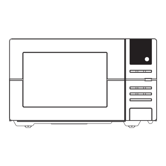
Page 5: External View
EXTERNAL VIEW 1. OUTER DIMENSION - KOR-6L5K3S/KOR-6L5K5S... -
Page 6: Features Diagram
2. FEATURES DIAGRAM - KOR-6L5K3S/KOR-6L5K5S 1 Door latch - When the door is closed, it will 8 Roller guide - This must always be used for automatically shut off. If the door is opened cooking together with the glass cooking tray. -
Page 7: Control Panel
3. CONTROL PANEL - KOR-6L5K3S/KOR-6L5K5S 1 DISPLAY - Cooking time, power level are dis- 6 ONE TOUCH COOK - Used to cook or reheat played. specific quantities of food. 2 AUTO COOK - Used to cook or reheat many of 7 TIME SET BUTTON - Used to set the cooking favorite food. -
Page 8: Installation
• This appliance is supplied with cable of special type, which, if damaged, must be repaired with cable of same type. Such a cable can be purchased from DAEWOO and must be installed by a qualified person. 6. Examine the oven after unpacking for any damage such as: A misaligned door, broken door or a dent in cavity. -
Page 9: Operations And Functions
OPERATIONS AND FUNCTIONS 1. Connect the mains lead to an electrical outlet. 2. After placing the food in a suitable container, open the oven door and put it on the glass tray. The glass tray must always be in place during cooking. 3. -
Page 10: Disassembly And Assembly
DISASSEMBLY AND ASSEMBLY Cautions to be observed when troubleshooting. Unlike many other appliances, the microwave oven is high-voltage, high-current equipment. It is completely safe during normal operation. However, carelessness in servicing the oven can result in an electric shock or possible danger from a short circuit. You are asked to observe the following precautions carefully. - Page 11 1. To remove cabinet 1) Remove four screws on cabinet back. 2) Pull the cabinet backward. 2. To remove door assembly 1) Remove two screws which secure the stopper hinge top. 2) Remove the door assembly from top plate of cavity. 3) Reverse the above for reassembly.
- Page 12 3. To remove door parts. - KOR-6L5K3S/KOR-6L5K5S REF No. PART CODE PART NAME DESCRIPTION Q’TY REMARK 3511730270 DOOR AS KOR-6L5K3S 3511730350 DOOR SUB AS KOR-6L5K3S 3517012700 BARRIER SCREEN *O TEMP GLASS T3.2 3515204120 STOPPER HINGE *T AS KOR-6L0B1A 3511706130 DOOR PAINTING AS...
- Page 13 4. Method to reduce the gap between the door seal and the oven front surface. (1) To reduce gap located on part ‘A’ • Loosen two screws on the stopper hinge top, and then push the door to contact the door seal to the oven front sur- face.
- Page 14 5. To remove control panel parts. - KOR-6L5K3S/KOR-6L5K5S B07 B08 REF No. PART CODE PART NAME DESCRIPTION Q’TY REMARK PKCPSWZA40 CONTROL-PANEL AS KOR-6L5K3S KOR-6L5K3S PKCPSWZA90 KOR-6L5K5S KOR-6L5K5S 3516739320 CONTROL-PANEL SUB AS KOR-6L5K3S 3515503500 WINDOW DISPLAY 3516921100 BUTTON SUB AS KOR-6L5K3S...
- Page 15 6. To remove guide wind parts. - KOR-6L5K3S/KOR-6L5K5S REF No. PART CODE PART NAME DESCRIPTION Q’TY REMARK 3512524830 GUIDE WIND AS KOR-6L0B3S KOR-6L5K3S 3512529420 KOC-9Q0T7R KOR-6L5K5S 3512527600 GUIDE WIND 3963514350 MOTOR SHADED POLE 230V 60Hz MW10CA-M04 7121402511 SCREW TAPPING T2S PAN 4X25 MFZN...
- Page 16 7. To remove high voltage capacitor. 1) Remove the screw which secure the grounding ring terminal of the H.V. diode and the capacitor holder. 2) Remove the H.V. diode from the capacitor holder. 3) Reverse the above steps for reassembly. ◆...
- Page 17 9. To remove wind guide assembly. 1) Remove the screw for earthing. 2) Remove the noise filter from the wind guide. 3) Remove the screw which secure the wind guide assembly. 4) Draw forward the wind guide assembly. 5) Pull the fan from the motor shaft. 6) Remove two screws which secure the motor shaded pole.
-
Page 18: Interlock Mechanism And Adjustment
The door lock mechanism is a device which has been specially designed to completely eliminate microwave radiation when the door is opened during operation, and thus to perfectly prevent the danger resulting from the leakage of microwave. - KOR-6L5K3S/KOR-6L5K5S Primary... -
Page 19: Troubleshooting Guide
TROUBLESHOOTING GUIDE Following the procedure below to check if the oven is defective or not. 1. Check grounding before trouble checking. 2. Be careful of the high voltage circuit. 3. Discharge the high voltage capacitor. 4. When checking the continuity of the switches, fuse or high voltage transformer, disconnect one lead wire from these parts and check continuity with the AC plug removed. - Page 20 CONDITION CHECK RESULT CAUSE REMEDY Replace Defective mag- Outlet has Check continuity of magnetron Continuity netron proper volt- age Fuse does not Replace blow. Check continuity of Open power sup- Continuity ply cord power supply cord Replace Normal Defective touch control circuit Replace Malfunction of sec-...
- Page 21 (TROUBLE 3) No microwave oscillation even though fan motor rotates. CONDITION CHECK RESULT CAUSE REMEDY Continuity Replace Check continuity of high Defective high microwave voltage capacitor terminals voltage trans- oscillation with wires removed former Continuity in Replace Check continuity of high voltage Defective high backward rectifier in forward and backward...
- Page 22 (TROUBLE 4) The following visual conditions indicate a probable defective touch control circuit 1. Incomplete segments (1) Segments missing (2) Partical segments missing (3) Digit flickering other than normal display slight flickering (4) “ :0” does not display when press and hold ZERO ON button until display is turned on and beep sounds.
-
Page 23: Measurement And Test
MEASUREMENT AND TEST 1. MEASUREMENT OF THE MICROWAVE POWER OUTPUT Microwave output power can be checked by indirectly measuring the temperature rise of a certain amount of water exposed to the microwave as directed below. PROCEDURE 1. A cylindrical container of borosilicate glass is used for the test. It has a maximum thickness of 3mm, an external diameter of approximately 190mm and a height of approximately 90mm. -
Page 24: Microwave Radiation Test
2. MICROWAVE RADIATION TEST CAUTION : 1. Make sure to check the microwave leakage before and after repair of adjustment. 2. Always start measuring of an unknown field to assure safety for operating personnel from microwave energy. 3. Do not place your hands into any suspected microwave radiation field unless the safe density level is known. 4. -
Page 25: Component Test Procedure
1. High voltage transformer (1) Remove connections from the transformer terminals and check continuity. (2) Normal readings should be as follows: Secondary winding ..Approx. 191Ω ±10%(KOR-6L5K3S)/193 Ω ±110%(KOR-6L5K5S) Filament winding ....................Approx. 0Ω Primary winding ...........2.5 Ω(KOR-6L5K3S)/2.5 Ω(KOR-6L5K5S) 2. High voltage capacitor (1) Check continuity of capacitor with meter on the highest OHM scale. -
Page 26: Wiring Diagram
WIRING DIAGRAM - KOR-6L5K3S/KOR-6L5K5S... -
Page 27: Printed Circuit Board
PRINTED CIRCUIT BOARD 1. CIRCUIT CHECK PROCEDURE 1. Low Voltage Transformer check • The low voltage transformer is located on the P.C.B. • Measuring condition: input voltage : 230V / Frequency : 50Hz Terminal Voltage LOAD NO LOAD 5-6-7 AC 25.3V AC 30.8V NOTE : 1. - Page 28 - KOR-6L5K3S/KOR-6L5K5S Measure Point...
- Page 29 3. When there is no microwave oscillation 1) When pressing START button, oven lamp does not turn on. Fan motor does not rotate, but cook indicator in display comes on. - Check method POINT STATE RELAY 2 ON 5V DC RELAY 2 OFF 15V DC 2) When pressing START button, oven lamp turns on.
-
Page 30: Pcb Circuit Diagram
2. PCB CIRCUIT DIAGRAM - KOR-6L5K3S/KOR-6L5K5S... - Page 31 5EPV035303 TRANS POWER DMR-631FS J1,2,4,5,8,9,11,12 85801052GY WIRE COPPER 1/0.52 TIN COATING SJ1 (KOR-6L5K3S) 85801052GY WIRE COPPER 1/0.52 TIN COATING SJ2 (KOR-6L5K5S) 85801052GY WIRE COPPER 1/0.52 TIN COATING J3,6,7,10,J13~J15 85801053GY WIRE COPPER 1/0.52 TIN COATING 5SC0101123 SW RELAY G5G-1A-DT DC12V RY2,RY3...
-
Page 32: Exploded View And Parts List
EXPLODED VIEW AND PARTS LIST 1. DOOR ASSEMBLY Refer to Disassembly and assembly. 2. CONTROL PANEL ASSEMBLY Refer to Disassembly and assembly. 3. GUIDE WIND ASSEMBLY Refer to Disassembly and assembly. 4. TOTAL ASSEMBLY - KOR-6L5K3S/KOR-6L5K5S F30 F29... - Page 33 - KOR-6L5K3S/KOR-6L5K5S PART CODE PART NAME DESCRIPTION QíTY REMARK 3511730270 DOOR AS KOR-6L5K3S KOR-6L5K3S KOR-6L5K5S KOR-6L5K5S PKCPSWZA40 CONTROL-PANEL AS KOR-6L5K3S KOR-6L5K3S PKCPSWZA90 KOR-6L5K5S KOR-6L5K5S 3512524830 GUIDE WIND AS KOR-6L5K3S KOR-6L5K3S 3512529420 KOR-6L5K5S KOR-6L5K5S 3510808410 CABINET AS KOR-6L0B1A 3516117410 CAVITY AS...
- Page 34 DAEWOO ELECTRONICS CORP. 1-2, Jeo-dong 1(il)-ga, Jung-gu, Seoul, Korea C.P.O. BOX 8003 SEOUL, KOREA TELEX: DWELEC K28177-8 CABLE: “DAEWOOELEC” S/M NO. : PRINTED DATE: Aug. 2012...
- Page 35 ABOUT THIS MANUAL ABOUT THIS MANUAL...
Need help?
Do you have a question about the KOR-6L5K5S and is the answer not in the manual?
Questions and answers