Table of Contents
Advertisement
Quick Links
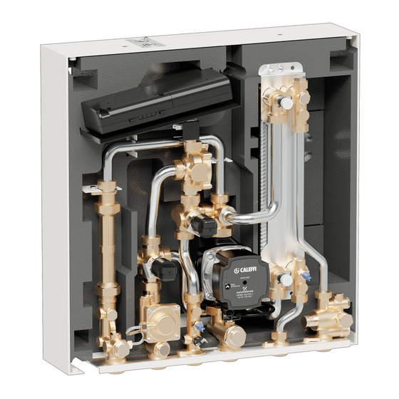
SATK series wall-mounted direct Heat Interface Unit
INSTRUCTIONS FOR INSTALLATION, COMMISSIONING AND MAINTENANCE
Product range
SATK22103
Direct wall-mounted HIU for LOW temperature
heating. Domestic hot water capacity 50 kW
SATK22105
Direct wall-mounted HIU for LOW temperature
heating. Domestic hot water capacity 60 kW
SATK22107
Direct wall-mounted HIU for LOW temperature
heating. For low temperature heating networks.
SATK22203
Direct wall-mounted HIU for MEDIUM temp.
heating. Domestic hot water capacity 50 kW
SATK22205
Direct wall-mounted HIU for MEDIUM temp.
heating. Domestic hot water capacity 60 kW
SATK22207
Direct wall-mounted HIU for MEDIUM temperature
heating. For low temperature heating networks
SATK22303
Direct wall-mounted HIU for HIGH temp.
heating. Domestic hot water capacity 50 kW
SATK22305
Direct wall-mounted HIU for HIGH temp.
heating. Domestic hot water capacity 60 kW
SATK22307
Direct wall-mounted HIU for HIGH temperature
heating. For low temperature heating networks.
SATK22403
Direct wall-mounted HIU for HIGH temp.
heating. Domestic hot water capacity 50 kW
With primary pump.
SATK22405
Direct wall-mounted HIU for HIGH temp.
heating. Domestic hot water capacity 60 kW
With primary pump.
SATK22407
Direct wall-mounted HIU for HIGH temperature
heating. For low temperature heating networks.
(1) Primary side head > 50 kPa, primary flow temperature 70°C,
DHW 10 - 50°C
All languages
are available on:
I
FR
NL
(1)
.
.
(1)
(1)
.
.
(1)
.
)
(1)
.
.
(1)
(1)
.
(1)
.
Function
The SATK series HIU allows independent control of heat regulation and
domestic hot water production within centralised heating systems or systems
served by district heating networks.
The heat interface unit features exceptional flexibility of installation and remote
controllable smart electronic functions designed to enhance efficiency of the
system.
CONTENTS
1
H0003192.01
www.caleffi.com
Serie SATK22
2
3
4
5
8
9
10
12
13
14
14
15
16
17
18
19
20
22
24
Advertisement
Table of Contents

Related Manuals for CALEFFI SATK22107


Summary of Contents for CALEFFI SATK22107
-
Page 1: Table Of Contents
DHW function - Comfort functions SATK22105 Direct wall-mounted HIU for LOW temperature heating. Domestic hot water capacity 60 kW Anti-legionella function SATK22107 Direct wall-mounted HIU for LOW temperature heating. For low temperature heating networks. SATK22203 Direct wall-mounted HIU for MEDIUM temp. -
Page 2: Safety Instructions
Medium temperature circuit flow High temperature circuit flow For the updated version of the technical documentation refer to www.caleffi.it. Medium temperature circuit return High temperature circuit return... -
Page 3: Dimensions - Technical Specifications
Dimensions = 3/4’’ Description of connections SATK22 technical specifications Medium: water Materials Max. percentage of glycol: Components: brass UNI EN12165 CW617N Maximum medium temperature: 90°C Connecting pipes: steel Frame: RAL 9010 painted steel Max. working pressure: - primary circuit: 1,0 MPa (10 bar) Exchanger: stainless steel brazed with copper - secondary circuit:... -
Page 4: Hydraulic Components And Diagram
Characteristic components SATK2210. (LOW temperature) Frame Electronic controller 2-way modulating valve - Heating 2-way modulating valve - DHW 130 mm heat meter template 1/4’’ F pressure port Return temperature probe Connection for M10x1 heat meter return probe Primary drain cock 10. - Page 5 Characteristic components SATK2230. (HIGH temperature) Frame Electronic controller 2-way modulating valve - Heating 2-way modulating valve - DHW 130 mm heat meter template 1/4’’ F pressure port Return temperature probe Connection for M10x1 heat meter return probe Primary drain cock 10.
-
Page 6: Hydraulic Installation
Hydraulic installation Notes for the installer The SATK series HIU is designed for installation in a sheltered domestic environment (or similar), therefore it cannot be installed or used outdoors, i.e. in areas directly exposed to the weather. Outdoor installation may cause malfunctioning and hazards. If the appliance is enclosed inside or between cabinets, sufficient space must be provided for routine maintenance procedures. - Page 7 Installation with template NOTE: Before installation, it is recommended to carry out accurate flushing of all the pipes of the system in order to remove any residue or impurities that could endanger correct operation of the HIU. In order to facilitate these operations a manual bypass flushing valve is available (code 789110). Connections on the bottom Connections on the top N.B.:...
-
Page 8: Electrical Installation
Electrical installation Connection to the electric supply The appliance is supplied with an electric supply cable which is not fitted with a plug. The appliance should be electrically connected to a 230 V (ac) single- phase + earth mains supply using the three-wire cable marked with the label as specified aside, observing the LIVE (L) - NEUTRAL (N) polarities and the earth connection. -
Page 9: Commissioning
Installation in the room Use the cable outlet provided for connection of the remote user interface to the electronic circuit board. The chrono-thermostat function has to be enabled through the remote control. Refer to the dedicated user manual for the procedure. Use of an external room thermostat An external room thermostat, if installed, must necessarily be with potential-free contact. -
Page 10: Remote User Interface Quick Guide
Remote user interface quick guide DISPLAY: BUTTONS: (set) Ora/giorno corrente (day/night) (set) Temperature di set point Current time/date Set diurno/notturno (set) (set) (day/night) k regolazione climatica Set point temperature Ora/giorno corrente Ora/giorno corrente Daytime/night-time setting (day/night) (day/night) k outside temperature compensation Temperature di set point Temperature di set point Set diurno/notturno... - Page 11 riscaldamento e funzione scaldamassetto “comfort” <set> Ora/giorno corrente <R> <day/night> Temperature di set point Set diurno/notturno k regolazione climatica <temp> <mode> Visualizzazione ACS ON/OFF temperature Risc. ON/OFF (set point ambiente + sonde) <prog> <reset> Programmazione oraria Reset errore riarmabile/funzione riscaldamento e funzione scaldamassetto “comfort”...
-
Page 12: Heating Function
alta/bassa temperatura Heating function DEFAULT SETTING: set point regulation (technical parameter t01 = 0) intervento limite temperatura ritorno When heating cycle activation is requested by the room thermostat, the circulation pump is powered while the modulating valve is opened gradually until the set point temperature is reached. In the high temperature models (SATK2230. -
Page 13: Dhw Function - Comfort Functions
DHW function The DHW cycle always takes priority over the heating cycle. DEFAULT SETTING: fixed DHW set point (parameter t06 = 0) When DHW cycle activation is requested, due to DHW tapping by the user (detected by the domestic water flow meter), the regulator modulates the valve opening in order to adjust the temperature detected by the domestic water probe to the selected set point value. -
Page 14: Anti-Legionella Function
Anti-legionella function DEFAULT SETTING: anti-legionella function OFF (technical parameter t08 = 0) Enabling the anti-legionella function by means of technical parameter t08 = 1, in time band 3:00 - 3:30: - the DHW set point will be temporarily increased to the maximum value (60°C) - the comfort/recirculation function will be forced ON. -
Page 15: Circulator - Curves And Setting
CARATTERISTICA PROPORZIONALE CARATTERISTICA COSTANTE Circulator - Curves and setting GIRI FISSI CURVA 1 (MIN) CURVA 2 A long press of the front key (>10 s) locks the pump setting, preventing The HIU is equipped with a Grundfos circulator model UPM3 AUTO possible incorrect modifications of the curve. -
Page 16: Auxiliary Microswitch
Auxiliary microswitch The HIU is equipped with a contact, driven by a relay incorporated in the circuit board, the intervention logic of which can be programmed in accordance with requirements by setting technical parameter t05. Each event linked to operation of the HIU is linked to a numerical value, according to the following table: Event/condition Value... -
Page 17: Modbus
The HIU offers a remote connectivity solution by means an RS-485 wired network and Modbus RTU communication protocol. On request, Caleffi will supply a map of the Mod-Bus registers and data transmission specifications so the product can be integrated in an existing BMS system. -
Page 18: Safety And Alarms
Errori Errori ento del relè Safety and alarms Errori Errori Errori Errori If the electronic circuit board detects a fault, the display shows the Safety thermostat cut-out (SATK2210.) error code concerned and the symbol Error code 69 Errori Errori ervento del relè Heating flow probe fault (SATK2210. -
Page 19: Electronic Circuit Board
IN/OUT RS-485 BUS EXP PORT OTS PREPAID ???????? Electronic circuit board IN/OUT Optional connections RS-485 BUS EXP PORT OTS PREPAID The electronic circuit board has a front door (shown in the adjacent ???????? figure) that provides access to the connectors related to HIU optional functions. -
Page 20: Periodic Maintenance
Periodic maintenance The following checks must be carried out at least once very 12 months, in accordance with the prescriptions of standard EN 806-5. OPERATIONS TO BE PERFORMED Force an actuators reset by switching the HIU power supply OFF and then ON Visually check for the absence of leaks and/or anomalies Check for possible active errors shown on the user interface Test correct operation of the pump/modulating valve by closing the thermostat contact or forcing it to close... - Page 21 19 for the connections. After concluding maintenance, proceed with the filling and checking operations described in the chapter “commissioning” (page 9) and fit the cover. If you require any information regarding spare parts, please contact Caleffi spa.
-
Page 22: Troubleshooting
Troubleshooting FAULT DESCRIPTION ALERTS POSSIBLE CAUSE OF FAULT OPERATIONS TO BE PERFORMED primary circuit shut-off valves closed open the valves modulating valve actuator disconnected from valve body reconnect actuator modulating valve actuator faulty call qualified personnel to have it replaced blinking DHW temperature probe cable inverted with heating probe restore correct connection... - Page 23 FAULT DESCRIPTION ALERTS POSSIBLE CAUSE OF FAULT OPERATIONS TO BE PERFORMED eratura ritorno alta/bassa temperatura heating cycle temperature set point too low increase set point mandata a punto sso impostazione temperatura di mandata chrono-thermostat temperature setting incorrect check programming of chrono-thermostat HIU strainer clogged call qualified personnel to have it serviced primary return temperature limitation intervention (the...
-
Page 24: Commissioning Check-List
Commissioning check-list Checks to be performed Is the heat interface unit properly secured to the wall? Has the system flushing been carried out? Check strainers and clean them if necessary Is the heat meter (if present) connected? Is the heat meter (if present) connected to the building datalogger (if required)? Is the DCW line fitted with a pressure reducing valve? Are the shut-off valves open? Has the visual inspection of the hydraulic sealing efficiency produced positive results?
Need help?
Do you have a question about the SATK22107 and is the answer not in the manual?
Questions and answers