Table of Contents
Advertisement
SATK series wall-mounted indirect Heat Interface Unit
INSTRUCTIONS FOR INSTALLATION, COMMISSIONING AND MAINTENANCE
All languages are available on:
Product range
SATK32103
Indirect wall-mounted HIU for instantaneous
domestic hot water production, capacity 50 kW
SATK32105
Indirect wall-mounted HIU for instantaneous
domestic hot water production, capacity 60 kW
(1)
Primary side head > 50 kPa, primary flow temperature 70°C,
DHW 10 - 50°C
I
FR
NL
(1)
.
(1)
.
Function
The SATK series HIU allows independent control of heat regulation and
domestic hot water production within centralised heating systems or systems
served by district heating networks.
The heat interface unit features exceptional flexibility of installation and remote
controllable smart electronic functions designed to enhance efficiency of the
system.
CONTENTS
H0003193
www.c leffi.com
SATK32 series
2
3
4
5
8
9
10
12
13
14
14
15
16
17
18
19
20
22
24
Advertisement
Table of Contents

Related Manuals for CALEFFI SATK32105


Summary of Contents for CALEFFI SATK32105
-
Page 1: Table Of Contents
Product range Auxiliary microswitch SATK32103 Indirect wall-mounted HIU for instantaneous domestic hot water production, capacity 50 kW Modbus SATK32105 Indirect wall-mounted HIU for instantaneous domestic hot water production, capacity 60 kW Safety and alarms Electronic circuit board Periodic maintenance Primary side head > 50 kPa, primary flow temperature 70°C, Troubleshooting DHW 10 - 50°C... -
Page 2: Safety Instructions
3 All hydraulic connections must be visually checked while pressurising the system. Vibration during transport may cause the connections to become loose. If a fitting needs to be tightened apply a proper tightening torque, otherwise the components may be damaged by overtightening. For the updated version of the technical documentation refer to www.caleffi.it. Key to symbols... -
Page 3: Dimensions - Technical Specifications
Dimensions 3/4” 1/2” Description of connections SATK32 technical specifications Medium: water Materials Max. percentage of glycol: Components: brass UNI EN12165 CW617N Maximum medium temperature: 90°C Connecting pipes: steel Frame: RAL 9010 painted steel Max. working pressure: - primary circuit: 1,6 MPa (16 bar) Exchanger: stainless steel brazed with copper - secondary circuit:... -
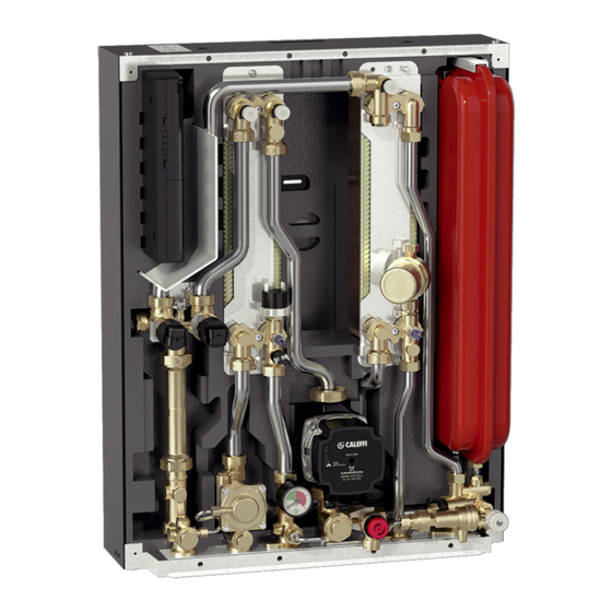
Page 4: Hydraulic Components And Diagram
Characteristic components Frame Controller Heating exchanger primary circuit air venting/drain Heating exchanger secondary circuit air venting/drain Heating exchanger Pressure switch 2-way modulating valve - Heating 2-way modulating valve - DHW Return temperature probe 10. Pressure gauge 11. Safety thermostat 12. 130 mm heat meter template 13. -
Page 5: Hydraulic Installation
Hydraulic installation Notes for the installer The SATK series HIU is designed for installation in a sheltered domestic environment (or similar), therefore it cannot be installed or used outdoors, i.e. in areas directly exposed to the weather. Outdoor installation may cause malfunctioning and hazards. If the appliance is enclosed inside or between cabinets, sufficient space must be provided for routine maintenance procedures. - Page 6 Installation procedure (without template) Secure the metal bracket supplied with the HIU to the wall using suitable wall anchors. Connections on the bottom Connections on the top Installation with template NOTE: Before installation, it is recommended to carry out accurate flushing of all the pipes of the system in order to remove any residue or impurities that could endanger correct operation of the HIU.
- Page 7 Conveyance of the safety relief valve The safety relief valve is equipped with a compression fitting suitable for 15 mm copper pipe and can be rotated in accordance with the HIU installation position. If SATK32 is installed with upward facing connections, use discharge pipe code 789832, specifically designed to route the valve drain line through the insulation shell, without damaging the internal electronic components.
-
Page 8: Electrical Installation
Electrical installation Connection to the electric supply The appliance is supplied with an electric supply cable which is not fitted with a plug. The appliance should be electrically connected to a 230 V (ac) single- phase + earth mains supply using the three-wire cable marked with the label as specified aside, observing the LIVE (L) - NEUTRAL (N) polarities and the earth connection. -
Page 9: Commissioning
Installation in the room Use the cable outlet provided for connection of the remote user interface to the electronic circuit board. The chrono-thermostat function has to be enabled through the remote control. Refer to the dedicated user manual for the procedure. Use of an external room thermostat An external room thermostat, if installed, must necessarily be with potential-free contact. -
Page 10: Remote User Interface Quick Guide
Remote user interface quick guide DISPLAY: BUTTONS: (set) Current time/date (day/night) Set point temperature Daytime/night-time setting k outside temperature compensation (temp) (mode) Temperature DHW ON/OFF display Heating ON/OFF (ambient set point + probes) (prog) (reset) Heating hourly Resettable error reset/floor slab programming and heating function “comfort”... - Page 11 Primary limit/set return temperature in Primary limit/set return temperature in Comfort function (ON/OFF or according heating mode (**) DHW mode (**) to weekly program) (see page 13) (*) if the thermostat function of the remote user interface is enabled. (**) if these set points cannot be changed you must set parameter t07 to value 0 in the technical menu (see “access to technical menu” below). Parameter t07= 1 “freezes”...
-
Page 12: Heating Function
Heating function HIU setting at HIGH/LOW temperature The HIU is set at LOW temperature by default (underfloor heating, parameter t00 = 1). To change this setting and supply a system with high temperature terminals go to the technical menu (see page 11) and set parameter t00 to 0. -
Page 13: Dhw Function - Comfort Functions
DHW function The DHW cycle always takes priority over the heating cycle. DEFAULT SETTING: fixed DHW set point (parameter t06=0) When DHW cycle activation is requested, due to DHW tapping by the user (detected by the domestic water flow meter), the regulator modulates the valve opening in order to adjust the temperature detected by the domestic water probe to the selected set point value. -
Page 14: Anti-Legionella Function
Anti-legionella function DEFAULT SETTING: anti-legionella function OFF (technical parameter t08 = 0) Enabling the anti-legionella function by means of technical parameter t08 = 1, in time band 3:00 - 3:30: - the DHW set point will be temporarily increased to the maximum value (60°C) - the comfort/recirculation function will be forced ON. -
Page 15: Circulator - Curves And Setting
Circulator - Curves and setting The HIU is equipped with a Grundfos circulator model UPM3 AUTO-L PERFORMANCE 15-70. By default, the circulator setting is with the maximum proportional head characteristic. Pressing the front key briefly produces the sequence of LEDs corresponding selected hydraulic... -
Page 16: Auxiliary Microswitch
Auxiliary microswitch The HIU is equipped with a contact, driven by a relay incorporated in the circuit board, the intervention logic of which can be programmed in accordance with requirements by setting technical parameter t05. Each event linked to operation of the HIU is linked to a numerical value, according to the following table: Event/condition Value... -
Page 17: Modbus
The HIU offers a remote connectivity solution by means an RS-485 wired network and Modbus RTU communication protocol. On request, Caleffi will supply a map of the Mod-Bus registers and data transmission specifications so the product can be integrated in an existing BMS system. -
Page 18: Safety And Alarms
Safety and alarms If the electronic circuit board detects a fault, the display shows the Safety thermostat cut-out error code concerned and the symbol Error code 69 Heating circuit pressure switch fault Error code 4 HIUs configured to support low temperature heating continuously monitor the safety thermostat controlling the flow temperature. -
Page 19: Electronic Circuit Board
Electronic circuit board Optional connections The electronic circuit board has a front door (shown in the adjacent figure) that provides access to the connectors related to HIU optional functions. N.B. before working on the circuit board you must disconnect the electric supply to the HIU. RS-485 BUS PREPAID 250Vac 3A... -
Page 20: Periodic Maintenance
Periodic maintenance The following checks must be carried out at least once very 12 months, in accordance with the prescriptions of standard EN 806-5. OPERATIONS TO BE PERFORMED Force an actuators reset by switching the HIU power supply OFF and then ON Visually check for the absence of leaks and/or anomalies Check for possible active errors shown on the user interface Test correct operation of the pump by closing the thermostat contact or forcing it to close... - Page 21 19 for the connections. After concluding maintenance, proceed with the filling and checking operations described in the chapter “commissioning” (page 9) and fit the cover. If you require any information regarding spare parts, please contact Caleffi spa.
-
Page 22: Troubleshooting
Troubleshooting FAULT DESCRIPTION ALERTS POSSIBLE CAUSE OF FAULT OPERATIONS TO BE PERFORMED primary circuit shut-off valves closed open the valves modulating valve actuator disconnected from valve body reconnect actuator modulating valve actuator faulty call qualified personnel to have it replaced blinking DHW temperature probe cable inverted with heating probe restore correct connection... - Page 23 FAULT DESCRIPTION ALERTS POSSIBLE CAUSE OF FAULT OPERATIONS TO BE PERFORMED heating cycle temperature set point too low increase set point chrono-thermostat temperature setting incorrect check programming of chrono-thermostat HIU strainer clogged call qualified personnel to have it serviced primary return temperature limitation intervention (the change the return temperature set point/disable the function following icon appears...
-
Page 24: Commissioning Check-List
Checks to be performed Is the heat interface unit properly secured to the wall? Has the system flushing been carried out? Check strainers and clean them if necessary Is the heat meter (if present) connected? Is the heat meter (if present) connected to the building datalogger (if required)? Is the DCW line fitted with a pressure reducing valve? Is the system protected by water hammer arresters? Are the shut-off valves open?
Need help?
Do you have a question about the SATK32105 and is the answer not in the manual?
Questions and answers