Advertisement
Quick Links
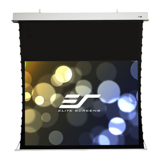
In-Ceiling Electric Motorized Front Projection Screen
Evanesce Tab-Tension Series
Important Safety & Warning Precautions
Make sure to read this user's guide and follow the procedures below.
Caution: The screen's Black Top Drop is already set to its maximum drop distance. There is NO extra
Black Top Drop in the roller. Please be aware of this as it will void your warranty with Elite Screens.
Unapproved changes or modifications (except for cutting the power cord for hardwire installations) to this
unit are prohibited and will void your warranty.
•
Please retain this user's guide for future reference.
•
To avoid damaging the unit, do not use with any unauthorized accessories not recommended by
the manufacturer.
•
Handle the unit carefully during transportation to avoid any damages.
•
To ensure safe and reliable operation, direct connection to a properly grounded power source is
advised.
•
The power outlet supplying power to the unit should be close to the unit and easily accessible.
•
Do not install the unit on uneven, inclined surfaces;
•
Do not install in damp places to avoid an electric shock or short circuit.
•
Do not place any heavy objects over the power cord.
•
Position the power cord properly to avoid creating a trip obstacle.
•
To avoid an electrical shock or fire, due to a loose contact or short circuit, do not overload the
power cord.
•
The internal & external parts of this unit are not end user serviceable. Do not attempt to
disassemble this unit by yourself. No one except authorized technicians can open and make
repairs to this unit.
•
Make sure the power source that this unit is connected to has a continuous power flow.
•
If there is need to use an extension cord, make sure the cord has an equal rating as the appliance
to avoid over heat.
•
Do not handle the power plug when your hands are wet or your feet are in contact with water.
•
Properly dispose of this equipment according to the environmental regulations in your area
when product is no longer of service.
Rev.071916-MZ
User's Guide
1
www.elitescreens.com
Advertisement

Summary of Contents for Elite Screens ITE139XW3-E8
- Page 1 Caution: The screen’s Black Top Drop is already set to its maximum drop distance. There is NO extra Black Top Drop in the roller. Please be aware of this as it will void your warranty with Elite Screens. Unapproved changes or modifications (except for cutting the power cord for hardwire installations) to this unit are prohibited and will void your warranty.
-
Page 2: Installation Warning
The installer must insure that proper mounting hardware is used to provide adequate strength suitable for the installation. Elite Screens is not liable for any faulty installations. For limit adjustment instructions, please contact our Technical Support Department at (877) 511-1211 Ext. 604 The Screen’s Top Black Drop is already set to its maximum drop distance. - Page 3 Evanesce Tab-Tension Series| Controls and Accessories A. IR Remote B. RF Remote C. Wall switch control box D. 5-12 volt trigger cable E. IR extended “eye” receiver F. Wireless 5-12v (3.5 mm) G. AAA batteries H. Bubble leveler mono trigger cable Screen operation Electric Current: Depending upon region, your Elite Screen will operate on 100v, 110v, or 220v voltage.
- Page 4 5. 5-12 volt trigger (Item D, Fig 4): The built-in 5-12V RJ45 Input trigger input allows your screen to synchronize its drop & rise with the projector’s power cycle. The screen deploys Fig.4 when the projector powers up and will retract when the projector powers down.
-
Page 5: Installation Instructions
Prong Power Cord (2-Prong Power Cord for some countries) for use in a non-concealed power outlet. If your installation will be entirely concealed (including power outlet), Elite Screens strongly recommends a hardwire connection. Please refer to the image below for both 110v & 220v wiring information. - Page 6 Optional Suspension Bar J-Hook (G) 1. Attach the Suspension Bar J- Hook (G) to the bottom of the Suspension Bar (D) and secure with the Hex Screw (B), Washer (E) and Hex Nut (F). 2. Attach the Suspension Bar J-Hook (G)to the Hanging Bracket (C) as shown in figure below. Install the Suspension Bars (D) to your ceiling according to their distance.
- Page 7 2. Mark the location of where the screen will be installed according to the distance (L) and then secure the bolt to the ceiling. 3. Install the screen to the screw bolt as shown in the figure below. B. Below ceiling installation instructions Measure and cut the ceiling installation space.
- Page 8 2. Drill 4 holes in the ceiling that correspond with the attachments on the various casing sizes. Install screw holes The ceiling wall 3. The expanding bolts (H) mount into thick wood beams, stone or concrete and will support the screen.
- Page 9 (J) to ensure a firm connection. Use thesocket wrench (N) to make sure that the bolts are firmly tightened. Ceiling Push Socket wrench (H) 5. Install plastic cover panel (O) to complete the installation. For local Elite Screens contact or Technical Support, please visit www.elitescreens.com Rev.071916-MZ www.elitescreens.com...


Need help?
Do you have a question about the ITE139XW3-E8 and is the answer not in the manual?
Questions and answers