Table of Contents
Advertisement
Quick Links
I N S TA L L AT I O N MA N UA L
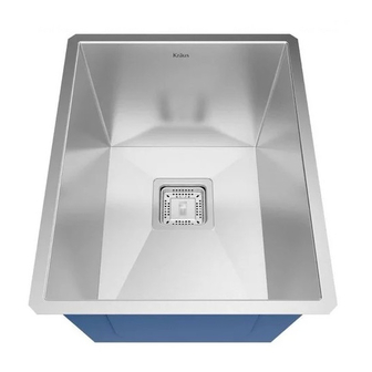
Zero-Radius Handmade Stainless
Steel Kitchen Sinks
(Pax™ and R0 PRO™ Series)
KHU15 & KHU15C / KHU19 & KHU19C / KHU23 &
KHU23C / KHU24L & KHU24CL / KHU29 & KHU29C
KHU32 & KHU32C / KHU322 & KHU322C
www.kraususa.com I toll free: 1.800.775.0703 I © 2014-2015 Kraus USA Inc. I REV. August 17, 2016
Advertisement
Table of Contents

Related Manuals for Kraus Pax Series


Summary of Contents for Kraus Pax Series
- Page 1 KHU15 & KHU15C / KHU19 & KHU19C / KHU23 & KHU23C / KHU24L & KHU24CL / KHU29 & KHU29C KHU32 & KHU32C / KHU322 & KHU322C www.kraususa.com I toll free: 1.800.775.0703 I © 2014-2015 Kraus USA Inc. I REV. August 17, 2016...
- Page 2 Thank you for your purchase We would like to take this opportunity to thank you for choosing Kraus. We hope that you are completely satisfied with your purchase, and enjoy it for years to come. If you have any questions, or require technical assistance, please contact us at 800.775.0703 and one of our representatives will be happy to help.
-
Page 3: Prior To Installation
Toll-Free: 800-775-0703 or Customerservice@kraususa.com The step-by-step guidelines in the installation instructions are a general reference for installing a Kraus Sink. Should there be any discrepancies, Kraus cannot be held liable. It is recommended to install all Kraus products by hiring a licensed professional. -
Page 4: Parts List
Putty Knife Tape Measure Pencil Scissors Screwdriver NOTE: Specialized tools may be necessary to install Kraus Stainless Steel Undermount sinks with countertop materials other than wood, marble, or granite Parts List • Cut-Out Template • Mounting Hardware • Bottom Grids •... - Page 5 Dimensions 13" 17" 14-1/2" 18-1/2" 95° 95° KHU15 & KHU15C KHU19 & KHU19C 14.5” x 18.5” x 10” 18.5” x 18.5” x 10” Min Cabinet Size: 18” Min Cabinet Size: 24” Drain Model #: ST-3 Drain Model #: ST-3 Optional Drain#: GDA-1 Optional Drain#: GDA-1 22-1/2"...
- Page 6 27" 30" 28-1/2" 31-1/2" 95° 95° KHU29 & KHU29C KHU32 & KHU32C 28.5” x 18.5” x 10” 31.5” x 18.5” x 10” Min Cabinet Size: 33” Min Cabinet Size: 36” Matching Grid: KBG-H29 Matching Grid: KBG-H32 Drain Model #: ST-3 Drain Model #: ST-3 Optional Drain#: GDA-1 Optional Drain#: GDA-1...
- Page 7 (Negative, Positive, or Flushed Reveal) 3/8“ Positive Reveal 3/8“ Positive Reveal 3/8“ Positive Reveal Zero Reveal Flushed/Zero Reveal Flushed/Zero Reveal Flushed/Zero Reveal 1/8“ Negative Reveal ative Reveal KRAUS Recommended Installation Type 1/8“ Negative Reveal 3/8”POSITIVE 3/8”POSITIVE 1/8“ Negative Reveal 3/8”POSITIVE 1/8”NEGATIV 3/8”POSITIVE 1/8”NEGATIVE 1/8”NEGATIV FLUSHED/ZERO 1/8”NEGATIV...
- Page 8 Step1 2. Position Template • Check the cut-out template against the actual sink to ensure a proper sized cut-out • Place the cut-out template in the desired location on the countertop NOTE: Make sure clearance is suitable for backsplash, faucet, and plumbing for the sink...
- Page 9 Step2 3. Trace Template • Trace template on countertop with a pencil...
- Page 10 Step3 4. Cut Countertop • Cut the opening in the countertop by carefully following the traced line Step3 Please use the appropriate saw that best fits your countertop NOTE: Step4 material Determine location for mounting brackets; space 1/2" (13mm)
- Page 11 Determine location for mounting brackets; space 5. Set up Mounting Brackets 3/8”POSITIVE 1/8”NEGATIVE • Turn countertop over and align sink with countertop. Decide location for mounting brackets Centerline • Mounting holes should be ½” from edge of sink Step5 Step6 1/2"...
- Page 12 Step6 7. Install Anchors • Insert anchors into drilled holes and lightly tap with a hammer until flush Step7 8. Secure Sink to Countertop • Use a bead of silicone (or preferred adhesive) around the rim of the sink. Check the alignment of the sink to the cutout in the countertop. Place sink over cutout hole and press firmly...
-
Page 13: Attach Mounting Hardware
9. Attach Mounting Hardware Step8 • Attach mounting hardware to secure bowl. Remove excess sealant from inside lip • Allow sealant to set for 30 – 60 minutes Use acetone or rubbing alcohol to remove any excess sealant NOTE:... - Page 14 Step9 10. Install Plumbing Fixtures • Connect drain to sink. Connect trap to drain. Connect water supply connections to faucet according to manufacturer’s instructions • Run water into sink and check for leaks...
- Page 15 Our customer service hours are Monday – Friday, 9am – 8pm EST. Be sure to visit our website at www.kraususa.com If you are a HOMEOWNER please contact a Kraus Customer Service Representative at: Kraus USA, Inc. 12 Harbor Park Drive...
- Page 16 Please take a moment to share your experience. Visit http://www.kraususa.com/review to let us know what you think about your new Kraus product. Contact Us to Learn More 1.800.775.0703 / www.kraususa.com / customerservice@kraususa.com Like & Follow KrausUSA Download the Kraus Care & Maintenance Guide at: http://www.kraususa.com/maintenance www.kraususa.com...
- Page 17 INSTALLATION MANUAL ™ Oletto Single Handle Commercial Style Kitchen Faucet KPF-2631 www.kraususa.com I Toll Free: 1.800.775.0703 I © 2017 Kraus USA Inc. I REV. November 20, 2017...
- Page 18 Congratulations on the purchase of your new Kraus plumbing fixture! Please keep the box and packaging materials until your product is completely installed. If you have any questions, require technical assistance, or have any problems with your product: DO NOT RETURN TO STORE Please contact our Customer Service Team 1-800-775-0703 / customerservice@kraususa.com...
-
Page 19: Tools You Will Need
8 5/16” • Make sure you have all necessary parts by checking the diagram and parts list. If (257mm) (21mm) any part is missing or damaged, please contact Kraus Customer Service at 800- 1 15/16” ∅ 775-0703 for a replacement 50mm) 1 3/8”... - Page 20 Diagram and Parts List A. Spray Head G. Weight B. Faucet Body H. Quick Connect C. Deck & Putty Plate I. Hex Wrench D. Supply Hose i1. 2.5mm E. Hot & Cold Waterlines i2. 4mm J. Base F. Spray Hose...
-
Page 21: Faucet Dimensions
Faucet Dimensions 11" 279mm 4 1/4" 9 1/4" 106.5mm 233mm 2 1/2" 62mm 1 3/8" 10 1/4" 35mm 260.5mm 9/16-24UNEF-2B Step 1A: Install base without deck & putty plate Insert base (J) into sink or countertop with “FR↑NT” facing forward. Tighten screws on base (J) with 4mm hex wrench (i2) until base is secure on sink or countertop... - Page 22 Step 1B: Install base with deck & putty plate Place a bead of clear silicone sealant (not included) around the edge of the putty plate (C). Secure deck & putty plate (C) on sink or countertop. Insert base (J) into hole of deck &...
- Page 23 Step 3: Secure faucet Align arrow on faucet body (B) with arrow on base (J). Attach faucet body (B) to base (J). Secure faucet body (B) by tightening the set screw with 2.5mm hex wrench (i1) Installer Tip: Please loosen set screw from faucet body (B) prior to securing to base (J) Note: “...
- Page 24 Step 4: Connect waterlines to main valve Thread hot & cold waterlines (E) onto angle stops. Tighten with adjustable wrench until snug. Turn on the angle stops and check for leaks (DO NOT TURN FAUCET ON) Installer Tip: Use two wrenches when securing waterlines to angle stops to prevent kinking, as shown in picture Cold...
- Page 25 Step 5: Connect quick connect Attach Quick Connect (H) with black end onto spray hose (F) until you hear a click. Attach the other end onto the supply hose (D) until you hear a click. Installer Tip: Remove the plastic caps from the supply hose D and spray hose F prior to attach the quick connect...
- Page 26 Step 6: Install Weight Attach weight (G) on the designated mark on the spray hose (F) Designated Mark...
- Page 27 Step 7: Flush Faucet Remove spray head (A). Hold tip of spray hose. Turn faucet on for 1 minute to flush any debris. Reconnect spray head (A)
-
Page 28: Replacement Part List
Replacement Part List 1. Spray Head 2. Plastic Sleeve 3. Spray Hose 4. Set Screw 5. Catridge 6. Locking Nut 7. Catridge Cover 8. Metal Handle 9. A Index Button B Set Screw 10. Quick Connect Assembly 11. Cover Plate 12. -
Page 29: Troubleshooting
Do not clean with soaps, acid, polish, abrasives, or harsh cleaners Do not use cloth with a coarse surface Unscrew the aerator and clean when necessary *This installation manual is subject to change without further notice. Download the Kraus Care & Maintenance Guide at: http://www.kraususa.com/maintenance... - Page 30 Any product reported to the authorized dealer or to Kraus as being defective within the warranty period will be repaired or replaced with a product of equal value at the option of Kraus. This warranty extends to the original owner or end-user, and is not transferable to a subsequent owner.
- Page 31 (HI, AK, and Puerto Rico shipping charges may apply). International shipping fees are not included. COMMERCIAL WARRANTY Kraus extends the above warranty for a period of one (1) year to purchasers of products for industrial, commercial, and business use. All incidental or consequential damages are specifically excluded. No additional warranties, express or implied, are given, including but not limited to any implied warranty of merchantability or fitness for a particular purpose.
- Page 32 IMPORTANT Register Your Kraus Product Activate Your Warranty Access Premium Customer Support Get Product Information REGISTER TODAY http://www.kraususa.com/registration...
Need help?
Do you have a question about the Pax Series and is the answer not in the manual?
Questions and answers