Table of Contents
Advertisement
INSTALLATION, OPERATING AND
SERVICE INSTRUCTIONS FOR
CONDENSING HIGH EFFICIENCY
GAS - FIRED HOT WATER COMBI BOILER
TO THE INSTALLER: Affix these instructions adjacent to boiler.
TO THE CONSUMER: Retain these instructions for future reference.
As an ENERGY STAR
®
STAR
guidelines for energy efficiency established by the United States Environmental Protection Agency (EPA).
®
WARNING:
Improper installation, adjustment, alteration, service or maintenance can cause property damage,
injury, or loss of life. For assistance or additional information, consult a qualified installer, service agency or the
gas supplier. This boiler requires a special venting system. Read these instructions carefully before installing.
107774-01- 9/17
K2WTC
DIRECT VENT
Partner, U.S. Boiler Company has determined that the K2WTC Series meets the ENERGY
9700609
Price - $5.00
1
Advertisement
Table of Contents

Related Manuals for Burnham K2WTC


Summary of Contents for Burnham K2WTC
- Page 1 TO THE INSTALLER: Affix these instructions adjacent to boiler. TO THE CONSUMER: Retain these instructions for future reference. As an ENERGY STAR Partner, U.S. Boiler Company has determined that the K2WTC Series meets the ENERGY ® STAR guidelines for energy efficiency established by the United States Environmental Protection Agency (EPA).
- Page 2 IMPORTANT INFORMATION - READ CAREFULLY NOTE: The equipment shall be installed in accordance with those installation regulations enforced in the area where the installation is to be made. These regulations shall be carefully followed in all cases. Authorities having jurisdiction shall be consulted before installations are made.
- Page 3 WARNING Asphyxiation Hazard. Fire Hazard. Explosion Hazard. This boiler requires regular maintenance and service to operate safely. Follow the instructions contained in this manual. WARNING Asphyxiation Hazard. This boiler requires regular maintenance and service to operate safely. Follow the instructions contained in this manual. Improper installation, adjustment, alteration, service or maintenance can cause property damage, personal injury or loss of life.
- Page 4 WARNINGS FOR THE HOMEOWNER FOLLOW ALL INSTRUCTIONS and warnings DO NOT BLOCK AIR FLOW into or around the printed in this manual and posted on the boiler. boiler. Insufficient air may cause the boiler to produce carbon monoxide or start a fire. INSPECT THE BOILER ANNUALLY.
- Page 5 WARNINGS FOR THE INSTALLER INSTALL ALL GUARDS, cover plates, and READ THIS ENTIRE MANUAL before attempting installation, start-up, or service. Improper enclosures before operating the boiler. installation, adjustment, alteration, service, SIZE THE BOILER PROPERLY relative to the or maintenance may cause serious property design heat load or, if using domestic hot water damage, personal injury, or death.
-
Page 6: Table Of Contents
Table of Contents Product Description II. Specifications III. Before Installing Locating The Boiler Mounting The Boiler Air For Ventilation VII. Venting A. Vent System Design B. Design Requirements Unique to Horizontal Twin Pipe Venting Systems C. Design Requirements Unique to Vertical Venting Systems D. -
Page 7: Product Description
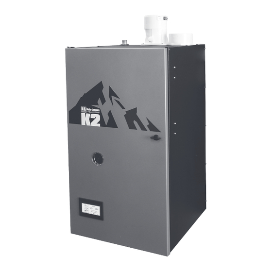
I. Product Description This boiler is a stainless steel gas fired condensing boiler designed for use in forced hot water heating systems requiring supply water temperatures of 180°F or less. In addition to providing water for space heat, this boiler also generates domestic hot water (DHW). This boiler may be vented vertically or horizontally with combustion air supplied from outdoors. It is not designed for use in gravity hot water systems or systems containing significant amounts of dissolved oxygen. -
Page 8: Before Installing
II. Specifications (continued) Table 2.2: Performance Specifications K2WTC Space Heating Ratings Domestic Hot Water (DHW) Ratings Hot Water Draw Limits, GPM Input, MBH Input, MBH Max. Heating Net AHRI Model Number Capacity, Water, 70°F 77°F 90°F AFUE, % Rise Rise Rise Min. -
Page 9: Locating The Boiler
III. Before Installing (continued) • For new radiant heating systems, refer to the radiant tubing manufacturer’s boiler sizing guidelines. • For system which includes an indirect water heater, make sure the boiler has the output called for by the indirect water heater manufacturer’s instructions. - Page 10 IV. Locating the Boiler (continued) Figure 4.1: Minimum Clearances To Combustible Construction 107774-01 - 9/17...
-
Page 11: Mounting The Boiler
V. Mounting The Boiler A. Wall Mounting CAUTION This boiler weighs as much as 126 pounds: • Two people are required to safely lift this boiler onto the wall mounting hook. • Make sure that wall mounting hook is anchored to a structure capable of supporting the weight of the boiler and attached piping when filled with water. - Page 12 V. Mounting The Boiler (continued) Figure 5.1 Wall Layout/Mounting Hole Location 107774-01 - 9/17...
- Page 13 V. Mounting The Boiler (continued) Figure 5.2 Boiler Mounting Bracket Installation / Boiler Wall Mounting 107774-01- 9/17...
-
Page 14: Air For Ventilation
VI . Air for Ventilation WARNING Outdoor combustion air must be piped to the air intake. Never pipe combustion air from areas containing contaminates such as swimming pools and laundry room exhaust vents. Contaminated combustion air will damage the boiler and may cause property damage, personal injury or loss of life. Air for combustion must always be obtained directly from outdoors (see Section VII for intake piping). -
Page 15: Venting
VII. Venting WARNING Asphyxiation Hazard. Failure to vent this boiler in accordance with these instructions could cause products of combustion to enter the building resulting in severe property damage, personal injury or death. Do not interchange vent systems or materials unless otherwise specified. The use of thermal insulation covering vent pipe and fittings is prohibited. - Page 16 VII. Venting A. Vent System Design (continued) Figure 7.0a: Horizontal Twin Pipe Figure 7.0b: Vertical Twin Pipe Figure 7.0c: Split Venting BOILER 107774-01 - 9/17...
- Page 17 VII. Venting A. Vent System Design (continued) • DuraVent PolyPro - ULC S636 listed Polypropylene special gas vent system. • Selkirk Polyflue - ULC S636 listed Polypropylene special gas vent system. • Centrotherm InnoFlue SW - ULC S636 listed Polypropylene special gas vent system. • DuraVent FasNSeal Flex - UL 1738 listed Stainless Steel special gas vent system. Use PVC and/or CPVC for the air intake system.
- Page 18 VII. Venting A. Vent System Design (continued) NOTICE Do not exceed maximum vent/combustion air system length. Refer to Tables 7.1B, 7.5, 7.13, and 7.21 in this section for maximum vent/combustion air system length. Use only vent and combustion air terminals and terminal locations shown in Tables 7.1B, 7.5, 7.13 and 7.21.
- Page 19 VII. Venting A. Vent System Design (continued) NOTICE Do not exceed maximum vent/combustion air system length. Refer to Tables 7.1B, 7.5, 7.13, and 7.21 in this section for maximum vent/combustion air system length. Use only vent and combustion air terminals and terminal locations shown in Tables 7.5, 7.13 and 7.21.
- Page 20 VII. Venting A. Vent System Design (continued) Supporting Pipe - Vertical and horizontal sections of pipe must be properly supported. Maximum support spacing is as follows: • Support CPVC/PVC horizontally and vertically every 4 feet. • Support DuraVent PolyPro horizontally near the female end of each straight section of pipe and vertically every 10 feet. •...
- Page 21 VII. Venting A. Vent System Design (continued) Figure 7.3a Figure 7.3b Figure 7.3c Figure 7.3: Expansion Loops for CPVC/PVC Pipe Figure 7.4: Wall Penetration Clearances for PVC Vent Pipe 107774-01- 9/17...
-
Page 22: Design Requirements Unique To Horizontal Twin Pipe Venting Systems
VII. Venting B. Design Requirements Unique to Horizontal Twin Pipe Venting Systems (continued) B. Design Requirements Unique to Horizontal Twin Pipe Venting Systems Table 7.5 summarizes all horizontal twin pipe vent options. Illustrations of horizontal twin pipe vent systems are shown in Figures 7.6 –... - Page 23 VII. Venting B. Design Requirements Unique to Horizontal Twin Pipe Venting Systems (continued) Table 7.5: Summary of Horizontal Twin Pipe Venting Options Vent Option 7.6, 7.7, Illustrated in Figure 7.9, 7.10 Pipe Vent Wall Wall Wall Wall Penetration through Intake Wall Wall Wall...
- Page 24 VII. Venting B. Design Requirements Unique to Horizontal Twin Pipe Venting Systems (continued) 2. Horizontal Vent and Air Intake Terminal Location - Observe the following limitations on the vent terminal location (also see Figure 7.11). When locating a concentric terminal, observe the limitations outlined below for “vent terminals”. •...
- Page 25 VII. Venting B. Design Requirements Unique to Horizontal Twin Pipe Venting Systems (continued) PVC VENT PIPE CPVC VENT PIPE PITCH VENT PIPE 1/4" PER (FIRST 30" + ELBOW) FOOT TOWARDS BOILER PVC AIR INTAKE PIPE ALTERNATE ORIENTATION PITCH INTAKE AWAY FROM BUILDING EXTERIOR BOILER IF POSSIBLE BOILER ROOM...
- Page 26 VII. Venting B. Design Requirements Unique to Horizontal Twin Pipe Venting Systems (continued) Figure 7.9: Duravent PolyPro, Selkirk, Polyflue or Centrotherm InnoFlue Horizontal Venting (Vent Options #2-4, Terminal Option A) PITCH VENT PIPE 5/8" PER FOOT TOWARDS BOILER 3" DURAVENT POLYPRO VENT PIPE PVC AIR INTAKE PIPE...
- Page 27 VII. Venting B. Design Requirements Unique to Horizontal Twin Pipe Venting Systems (continued) 107774-01- 9/17...
-
Page 28: Design Requirements Unique To Vertical Venting Systems
VII. Venting C. Design Requirements Unique to Vertical Venting Systems (continued) Figure 7.12: Snorkel Terminal Configuration (CPVC/PVC Vent Systems Only) C. Design Requirements Unique to Vertical Venting Systems Table 7.13a summarizes all vertical twin pipe vent options. Table 7.13.b summarizes vent options in which an abandoned B-vent chimney is used both as a chase for the vent pipe and as a conduit for combustion air. - Page 29 VII. Venting C. Design Requirements Unique to Vertical Venting Systems (continued) Table 7.13a: Summary of Vertical Twin Pipe Venting Options Option Illustrated in Figure 7.15, 7.17 7.17, 7.18 7.17 7.17 Pipe Vent Roof Roof Roof Roof Penetration through Intake Roof Roof Roof Roof...
- Page 30 VII. Venting C. Design Requirements Unique to Vertical Venting Systems (continued) Table 7.13b: Summary of Vertical “B-Vent Air Chase” Vent Options (B-Vent Chase MUST Be Sealed) Option Illustrated in Figure 7.19 7.20 Vent Roof Roof Pipe Penetration Through Structure Intake Roof Roof DuraVent...
- Page 31 VII. Venting C. Design Requirements Unique to Vertical Venting Systems (continued) Terminal Option J: DiversiTech Concentric Terminal (Acceptable for Vent Option 5) - This terminal is shown in Figure 7.16 and may be used with CPVC/PVC vent systems. See Section VII - E of this manual and the DiversiTech instructions provided with the terminal, for installation details.
- Page 32 VII. Venting C. Design Requirements Unique to Vertical Venting Systems (continued) Table 7.14: Equivalent Length of Flex Pipe Equivalent Length (ft) Flex Vent (1 ft): 3” DuraVent PolyPro Flex 2.0 ft 3” Centrotherm InnoFlue Flex 2.3 ft 3” Selkirk Polyflue 2.3 ft 3”...
- Page 33 VII. Venting C. Design Requirements Unique to Vertical Venting Systems (continued) Figure 7.15: Vertical CPVC/PVC Venting (Vent Option 5, Terminal Option H) Figure 7.16: Vertical CPVC/PVC Venting with IPEX Concentric Vent Terminal (Vent Option 5, Terminal Option I, J) 107774-01- 9/17...
- Page 34 VII. Venting C. Design Requirements Unique to Vertical Venting Systems (continued) Figure 7.17: Duravent PolyPro, Selkirk Polyflue or Centrotherm InnoFlue Vertical Single Wall PP Venting (Vent Options #6-8, Terminal Option H) Figure 7.18: Duravent PolyPro Vertical Venting with Concentric Terminal (Vent Option #6, Terminal Option K) 107774-01 - 9/17...
- Page 35 VII. Venting C. Design Requirements Unique to Vertical Venting Systems (continued) Figure 7.19: Duravent PolyPro B-Vent Air Chase System (Vent Option #9) Figure 7.20: Centrotherm InnoFlue B-Vent Air Chase System (Vent Option #10) 107774-01- 9/17...
-
Page 36: Design Requirements Unique To Split Vent Systems
VII. Venting D. Design Requirements Unique to Split Vent Systems (continued) D. Design Requirements Unique to Split Vent Systems Table 7.21 summarizes all split vent options. Illustrations of split vent systems are shown in Figures 7.22, 7.23, 7.24a and 7.25a. In addition to the requirements in Section VII - A, observe the following design requirements: 1. - Page 37 VII. Venting D. Design Requirements Unique to Split Vent Systems (continued) 5. Use of abandoned chimney as vent chase for flexible Stainless Steel venting (option 18) - Vent option 18 permits flexible Stainless Steel venting to be routed to the roof using an abandoned masonry type chimney. In this application, combustion air is drawn horizontally from a wall terminal. See Figure 7.25a. When using one of these options, observe the following requirements: • When a masonry chimney containing multiple flues is used as a chase, the flexible stainless vent installation is permitted through an adjacent UNUSED flue providing local authority having jurisdiction approves such installation. (Figure 25b) •...
- Page 38 VII. Venting D. Design Requirements Unique to Split Vent Systems (continued) Table 7.21: Summary of Split Vent System Options Option # Illustrated in Figure 7.22 7.22 7.22 7.22 7.23, 7.24 7.23, 7.24 Vent Roof Roof Roof Roof Roof Roof Pipe Penetration Through Structure Intake Wall...
- Page 39 VII. Venting D. Design Requirements Unique to Split Vent Systems (continued) Table 7.21: Summary of Split Vent System Options (cont.) Option # Illustrated in Figure 7.23, 7.24 7.23, 7.24 Vent Roof Roof Pipe Penetration Through Structure Intake Wall Wall DuraVent Centrotherm FasNSeal Vent...
- Page 40 VII. Venting D. Design Requirements Unique to Split Vent Systems (continued) FIRE STOP LISTED FOR USE WITH VENT SYSTEM PITCH 1/4" PER FT TOWARDS TRAP PVC AIR INTAKE PIPE Figure 7.22: Split Rigid Vent System (Vent Options 11-14) PVC AIR INTAKE PIPE Figure 7.23: Split Vent System (Flex in B-Vent Chase) Vent Options 15-17) 107774-01 - 9/17...
- Page 41 VII. Venting D. Design Requirements Unique to Split Vent Systems (continued) EXHAUST NOTE: DURAVENT POLYPRO FLEX COMPONENTS SHOWN. PPs FLEX CLEAN, TIGHT UNUSED CHIMNEY DURAVENT POLYPRO OUTSIDE WALL VENT PIPE PVC ELBOW PVC AIR WITH RODENT INTAKE PIPE SCREEN 12" MIN BASE SUPPORT AND ELBOW FOR PPs FLEX PIPE...
- Page 42 VII. Venting D. Design Requirements Unique to Split Vent Systems (continued) WITH CROWN 45° MAX BOILER CHIMNEY AND FOUNDATION ARE STRUCTURALLY SOUND Venting of Other Appliances (Or Fireplace) into Chase or Adjacent Flues Prohibited! BOILER Figure 7.24b: Flexible PP Masonry Chimney Chase Requirements 107774-01 - 9/17...
- Page 43 VII. Venting D. Design Requirements Unique to Split Vent Systems (continued) RAIN CAP FEMALE FLEX ADAPTER CLEAN, UNUSED, MASONRY CHIMNEY FLUE STAINLESS STEEL, DOUBLE LAYER, FLEXIBLE LINER EXTERIOR WALL PLATE RIGID SINGLE WALL VENT MALE FLEX ADAPTER OUTSIDE WALL ALTERNATE VENT PIPING PVC ELBOW WITH RODENT PVC AIR...
-
Page 44: Assembly Of Cpvc/Pvc Vent Systems
VII. Venting E. Assembly of CPVC/PVC Vent Systems (continued) E. Assembly of CPVC/PVC Vent Systems WARNING Asphyxiation Hazard. Failure to follow these instructions could cause products of combustion to enter the building, resulting in severe property damage, personal injury or death. Use all CPVC vent components for near-boiler vent piping before transitioning to Schedule 40 PVC pipe (ASTM 2665) components for remainder of vent system. - Page 45 VII. Venting E. Assembly of CPVC/PVC Vent Systems (continued) Figure 7.27: Vent Connections and Flue Gas Sample Cap Location Installation of Horizontal Fitting Terminals (Terminal Option A): a. See Figure 7.28 for proper orientation of twin pipe horizontal terminals. Outer edge of both terminals must be within 10” from wall surface.
- Page 46 VII. Venting E. Assembly of CPVC/PVC Vent Systems (continued) Figure 7.28: Installation of Standard Horizontal Terminals Figure 7.29: Installation of Standard Vertical Terminals 107774-01 - 9/17...
- Page 47 VII. Venting E. Assembly of CPVC/PVC Vent Systems (continued) 6. Installation of DiversiTech Low Profile Terminal (Terminal Option C) – See Figure 7.31: a. Use vent plate as a guide to locate the openings for the vent and air intake pipes, as well as to locate the holes for the mounting screws.
- Page 48 VII. Venting E. Assembly of CPVC/PVC Vent Systems (continued) Figure 7.30: Installation of IPEX Low Profile Terminal Through Sidewall Figure 7.31: Installation of DiversiTech Low Profile Terminal Through Sidewall 107774-01 - 9/17...
- Page 49 VII. Venting E. Assembly of CPVC/PVC Vent Systems (continued) Figure 7.32: Cutting IPEX and DiversiTech Concentric Vent Terminals Figure 7.33: Installation of IPEX and DiversiTech Concentric Terminal through Sidewall 107774-01- 9/17...
- Page 50 VII. Venting E. Assembly of CPVC/PVC Vent Systems (continued) Figure 7.34: Installation of IPEX and DiversiTech Concentric Terminal Through Roof 107774-01 - 9/17...
-
Page 51: Assembly Of Duravent Polypro Vent Systems
VII. Venting F. Assembly of DuraVent PolyPro Vent Systems (continued) F. Assembly of DuraVent PolyPro Vent Systems 1. This boiler has been approved for use with the DuraVent PolyPro single wall Polypropylene vent system to be provided by the installer. WARNING Asphyxiation Hazard. - Page 52 VII. Venting F. Assembly of DuraVent PolyPro Vent Systems (continued) 3. Installation of Air Intake System - Start assembly of the PVC air intake system at the boiler. Assembly of the air intake system is done in the same manner as the vent system except as follows: a. Drill a 7/32” clearance hole into the front side of the air intake adapter. Insert the first piece of PVC air intake pipe into the air intake connection and drill a 1/8”...
- Page 53 VII. Venting F. Assembly of DuraVent PolyPro Vent Systems (continued) Figure 7.36: Installation of Duravent PolyPro UV Resistant Single Wall Horizontal Terminal Figure 7.37: Installation of Duravent PolyPro UV Resistant Single Wall Vertical Terminal 107774-01- 9/17...
- Page 54 VII. Venting F. Assembly of DuraVent PolyPro Vent Systems (continued) 6. Installation of DuraVent PolyPro Horizontal Concentric Vent Terminal (Terminal Option D) - Install PolyPro Horizontal Concentric Termination Kit #3PPS-HK (Figure 7.39) as follows: a. At the planned location cut a 5-1/8” round hole for the 3” terminal in the exterior wall. (See Section VII - A of this manual for permitted terminal locations).
- Page 55 VII. Venting F. Assembly of DuraVent PolyPro Vent Systems (continued) Figure 7.39: Installation of Duravent PolyPro Concentric Vent Terminal Through Sidewall Figure 7.40: Installation of Duravent PolyPro Concentric Terminal Through Roof 107774-01- 9/17...
-
Page 56: Assembly Of Selkirk Polyflue Vent Systems
VII. Venting F. Assy of DuraVent PolyPro & G. Selkirk Polyflue Vent Systems (continued) 8. Installations using PolyPro-flex (Vent Options 9 & 15): WARNING Asphyxiation Hazard. When using PolyPro flex, observe the following precautions: • PolyPro flex may be damaged by handling at low temperatures. Do not bend, uncoil, or attempt to install if it has been stored at a temperature below 42°F without allowing it to warm to a higher temperature first. - Page 57 VII. Venting G. Assembly of Selkirk Polyflue Vent Systems (continued) 3. Installation of Air Intake System - Start assembly of the PVC air intake system at the boiler. Assembly of the air intake system is done in the same manner as the vent system except as follows: a. Drill a 7/32” clearance hole into the front side of the air intake adapter. Insert the first piece of PVC air intake pipe into the air intake connection and drill a 1/8”...
- Page 58 VII. Venting G. Assembly of Selkirk Polyflue Vent Systems (continued) 6. Installations using flexible Polyflue (Vent Option 16): WARNING Asphyxiation Hazard. When using Polyflue flex, observe the following precautions: • Polyflue flex may be damaged by handling at low temperatures. Do not bend, uncoil or attempt to install if it has been stored at a temperature below 42°F without allowing it to warm to a higher temperature first.
- Page 59 VII. Venting G. Assembly of Selkirk Polyflue Vent Systems (continued) Figure 7.42: Installation of Selkirk Polyflue UV Resistant Single Wall Horizontal Terminal Figure 7.43: Installation of Selkirk Polyflue UV Resistant Single Wall Vertical Terminal 107774-01- 9/17...
-
Page 60: Assembly Of Centrotherm Innoflue Vent Systems
VII. Venting H. Assembly of Centrotherm InnoFlue Vent Systems This boiler has been approved for use with the Centrotherm InnoFlue single wall Polypropylene vent system to be provided by the installer. WARNING Asphyxiation Hazard. Follow these instructions and the installation instructions included by the original Polypropylene venting component manufacturers, Centrotherm. - Page 61 VII. Venting H. Assembly of Centrotherm InnoFlue Vent Systems 3. Installation of Air Intake System - Start assembly of the PVC air intake system at the boiler. Assembly of the air intake system is done in the same manner as the vent system except as follows: a. Drill a 7/32” clearance hole into the front side of the air intake adapter. Insert the first piece of PVC air intake pipe into the air intake connection and drill a 1/8”...
- Page 62 VII. Venting H. Assembly of Centrotherm InnoFlue Vent Systems Figure 7.45: Installation of Centrotherm InnoFlue UV Stabilized Single Wall Horizontal Terminal Figure 7.46: Installation of Centrotherm InnoFlue UV Stabilized Single Wall Vertical Terminal 107774-01 - 9/17...
- Page 63 VII. Venting H. Assembly of Centrotherm InnoFlue Vent Systems Installations using InnoFlue Flex (Vent Options 10 & 17): WARNING Asphyxiation Hazard. When using InnoFlue Flex, observe the following precautions: • InnoFlue Flex may be damaged by handling at low temperatures. Do not bend, uncoil or attempt to install if it has been stored at a temperature below 42°F without allowing it to warm to a higher temperature first.
-
Page 64: Assembly Of Stainless Steel Vent Systems
VII. Venting I. Assembly of Stainless Steel Vent Systems I. Assembly of Stainless Steel Vent Systems This boiler has been approved for use with Duravent FasNSeal Flex Stainless Steel vent systems to be provided by the installer. WARNING Asphyxiation Hazard. Follow these instructions and the installation instructions included by the original stainless steel venting component manufacturer, DuraVent. - Page 65 VII. Venting I. Assembly of Stainless Steel Vent Systems (continued) d. When flexible stainless steel pipe is used for combustion product venting, it must be installed at vertical or near vertical orientation. This will insure proper condensate flow back towards the boiler. e. Follow flexible stainless steel pipe manufacturer specific instructions regarding application/listing, permits, minimum clearances to combustibles, installation details (proper joint assembly, pipe support and routing, gasket and fitting installation, optional tooling availability/usage, routing through masonry combination of combustion product venting and combustion air supply). f. When there is a conflict between flexible stainless steel pipe manufacturer installation instructions and boiler installation, Operating and Service Instructions, the more restrictive instructions shall govern. WARNING Asphyxiation Hazard.
-
Page 66: Condensate Trap And Drain
VII. Venting J. Condensate Trap and Drain Line (continued) J. Condensate Trap and Drain Line All condensate which forms in the boiler or vent system passes through the heat exchanger and out of a bottom drain port which is connected to the condensate trap with a hose. This trap allows condensate to drain from the heat exchanger while retaining flue gases in the boiler. This trap is an integral part of the boiler but must be connected to a drain pipe as shown in Figure 7.47. -
Page 67: Removing An Existing Boiler From Common Chimney
VII. Venting K. Removing an Existing Boiler From a Common Chimney (continued) K. Removing an Existing Boiler From a Common Chimney This section only applies if this boiler is replacing an existing boiler that is being removed from a common chimney. In some cases, when an existing boiler is removed from a common chimney, the common venting system may be too large for the remaining appliances. -
Page 68: Gas Piping
VIII. Gas Piping WARNING Explosion Hazard. Failure to properly pipe gas supply to boiler may result in improper operation or leaks of flammable gas. Gas supply to boiler and system must be absolutely shut off prior to installing or servicing boiler gas piping. Always assure gas piping is absolutely leak free and of the proper size and type for the connected load. - Page 69 VIII. Gas Piping (continued) CAUTION Support the weight of the gas line piping independently from the boiler gas connection fitting located on the bottom of the boiler. If an additional regulator is used to reduce boiler inlet pressure below 1/2 psig (3.4 kPa) it must be at least 6 to 10 ft.
-
Page 70: System Piping
IX. System Piping A. General System Piping Precautions WARNING Failure to properly pipe boiler may result in improper operation and damage to boiler or structure. Install boiler so that the gas ignition system components are protected from water (dripping, spraying, rain, etc.) during boiler operation and service (circulator replacement, etc.). -
Page 71: Standard Piping Installation Requirements
IX. System Piping (continued) B. Standard Piping Installation Requirements Observe the following requirements when installing the boiler piping: Relief Valve (Required) – The relief valve is shipped loose and must be installed in the location shown in Figure 9.0. Pipe the outlet of the relief valve to a location where water or stream will not create a hazard or cause property damage if the valve opens. - Page 72 IX. System Piping (continued) Drain Valve (required) – Install the drain valve (provided by the installer) as shown in Figure 9.2. Low Water Cut-off (may be required by local jurisdiction) – Protection of this boiler against low water and/or inadequate flow is provided by the UL353 certified flow switch built into the boiler. This is a water tube boiler and this flow switch is therefore the only effective way to provide such protection. Section HG614(c ) of the 2015 ASME boiler and Pressure Vessel Code recognizes the use of a listed flow switch in lieu of a low water cut-off on water tube boilers.
-
Page 73: Near Boiler Piping Design
IX. System Piping (continued) C. Near Boiler Piping Design Proper operation of this boiler requires that the water flow rate through it remain within the limits shown in Table 9.1 any time the boiler is firing. At flow rates below the minimum shown, the boiler’s flow switch and/or temperature rise limit function may prevent the boiler from firing. Flow rates through the boiler in excess of the maximum shown in Table 9.1 can result in excessive noise or erosion damage to piping There are two basic methods that can be used to pipe this boiler into the system. Method #1 (primary-secondary piping) is always preferred. - Page 74 IX. System Piping (continued) 107774-01 - 9/17...
- Page 75 IX. System Piping (continued) Example – A 135MBH model is to be connected to a heating system as shown in Figure 9.5. A total of 20 ft of straight pipe will be installed between the boiler and the system loop. Count all fittings in the boiler loop (shaded in Figure 9.5): 4 90°...
- Page 76 IX. System Piping (continued) 107774-01 - 9/17...
- Page 77 IX. System Piping (continued) Method 2: Direct Connection to Heating System (Generally NOT Recommended) In some relatively rare cases it may be possible to connect this boiler directly to the heating system as is done with conventional boilers (Figure 9.6). If this is done, the flow rate through the boiler will equal the flow rate through the system. The flow rate through the system must therefore always remain within the limits shown in Table 9.1. For this reason, the pressure drop through the entire system must be known. This method is generally not recommended because it is often very difficult to accurately calculate the pressure drop through the system.
- Page 78 IX. System Piping (continued) Note: These curves show the flow that can be achieved through the boiler as a function of the pressure drop through the connected piping. Flow (GPM) Figure 9.7a: 135 Net Circulator Performance Curve (Taco 0011) Flow (GPM) Figure 9.7b: 150/180 Net Circulator Curve (Taco 0013) 107774-01 - 9/17...
-
Page 79: Piping For Special Situations
IX. System Piping (continued) D. Piping for Special Situations System containing oxygen - Many hydronic systems contain enough dissolved oxygen to cause severe corrosion damage to a boiler. Some examples include: • Radiant systems that employ tubing without an oxygen barrier. •... -
Page 80: Domestic Hot Water Piping
X. Domestic Hot Water Piping DANGER - SCALD HAZARD Under certain conditions this boiler can deliver domestic hot water (DHW) at temperatures in excess of the DHW set point on the boiler control. An installer-supplied, ASSE 1017 or ASSE 1070 certified tempering valve is therefore REQUIRED as part of this boiler’s installation. - Page 81 X. Domestic Hot Water Piping (continued) Figure 10.1: Domestic Hot Water Piping 107774-01- 9/17...
-
Page 82: Wiring
XI. Wiring DANGER Electrical Shock Hazard. Positively assure all electrical connections are unpowered before attempting installation or service of electrical components or connections of the boiler or building. Lock out all electrical boxes with padlock once power is turned off. WARNING All wiring and grounding must be done in accordance with the authority having jurisdiction or, in the absence of such requirements, with the National Electrical Code /NFPA 70). - Page 83 XI. Wiring (continued) 2) Low Voltage Connections – Commonly used low voltage field connections are located on the low voltage PCB and are shown in Figure 11.3 and listed from left to right: 1 Heat T’Stat - 24VAC heating thermostat 2 Heat T’Stat - 24VAC heating thermostat 3 DHW Stat - No field connection 4 DHW Stat - No field connection 5 External Limit - Field supplied low voltage safety limit contacts (1) 6 External Limit - Field supplied low voltage safety limit contacts (2) 7 Outdoor Sensor - Tasseron TSA00AA Outdoor Temperature Sensor (1) 8 Outdoor Sensor - Tasseron TSA00AA Outdoor Temperature Sensor (2)
- Page 84 XI. Wiring (continued) Figure 11.2: Line Voltage Field Connections Figure 11.3: Low Voltage PCB Terminal Connections 107774-01 - 9/17...
- Page 85 XI. Wiring (continued) c) Low water cut-off wiring – Although not necessary to protect this boiler (see Part IX), some jurisdictions may insist that a low water cut-off (LWCO) be installed with this boiler. There are two ways to wire a LWCO into this boiler: •...
- Page 86 XI. Wiring (continued) Figure 11.4a: 120 Volt LWCO Field Wiring Figure 11.4b: 24 Volt LWCO Field Wiring Figure 11.5: J3 Field Wiring 107774-01 - 9/17...
- Page 87 XI. Wiring (continued) 120VAC/60Hz/1Ph R7910B Boiler Control J4‐6 J4‐7 P1‐5 6.3A Slo Ground screw in Blow In‐ boiler J‐box Line Fuse System Pump P1‐2 P1‐1 J4‐4 J4‐5 P5‐1 BP‐1 BP‐2 P5‐4 Boiler Pump J4‐2 J4‐3 P5‐7 ZV‐1 ZV‐2 Combustion Fan (120V Conn.) 3‐Way Zone Valve P3‐8 P3‐7 Internal, non replaceable 2 amp L2‐1 L2‐3 Ground screw AT140B on boiler frame L3‐1 L3‐2...
- Page 88 XI. Wiring (continued) 107774-01 - 9/17...
- Page 89 XI. Wiring (continued) 107774-01- 9/17...
- Page 90 XI. Wiring (continued) Table 11.8: Internal Wire Connection Markings Cross Reference Table WIRE NO. IN WIRE NO. IN WIRE MARKING WIRE MARKING FIG. 11.7 FIG 11.7 1 RD J8-8/P4-1, P4-1/SUP-1 20 BK SPL BK-1/P1-2, P1-2/120V 2 VI J9-4/P4-2, P4-2/FLUE-1 20a BK SPL BK-1/L2-1 3 RD J2-2/P4-3,...
- Page 91 XI. Wiring (continued) Figure 11.9: TACO SR504 or Equivalent Zone Panel Wiring Connection Diagram 107774-01- 9/17...
- Page 92 XI. Wiring (continued) Figure 11.10: Sage Zone Control Circulator Panel Wiring Connection Diagram 107774-01 - 9/17...
-
Page 93: Start-Up And Checkout
XII. Start-Up and Checkout WARNING Completely read, understand and follow all instructions in this manual before attempting start-up. NOTICE Safe lighting and other performance criteria were met with the gas train assembly provided on the boiler when the boiler underwent the tests specified in Z21.13. Use the following procedure for initial start-up of the boiler: Verify that the venting, water piping, gas piping and electrical system are installed properly. - Page 94 XII. Start-Up and Checkout (continued) DANGER Asphyxiation Hazard. Failure to properly convert this boiler for use on LP gas can cause unreliable operation at elevated carbon monoxide (CO) levels, resulting in personal injury or death. NOTICE To minimize the risk of premature heat exchanger failure, observe the following water chemistry requirements: 1.
- Page 95 XII. Start-Up and Checkout (continued) MANUAL AIR VENT ATTACH 1/4" ID CLEAR TUBING TO HOSE BARB AND ROUTE TO SAFE PLACE AWAY FROM CONTROLS BEFORE OPENING VENT. FLAME ROD Figure 12.1: Location of Manual Air Vent 11) Start the boiler using the lighting instructions on page 100. With the boiler powered up, and with no call for heat, the display should look like Figure 12.2a.
- Page 96 XII. Start-Up and Checkout (continued) Boiler /Combi Status kbtu Detail Standby Help Energy Save On High Efficiency On Adjust Figure 12.2a: Home Screen at Power-Up (No Call for Heat) Boiler /Combi Status kbtu Detail Central Heat Help Energy Save On High Efficiency On Adjust Figure 12.2b: Home Screen on Heat Demand...
- Page 97 XII. Start-Up and Checkout (continued) TUBE TO AIR PROVING SWITCH GAS OUTLET ("OFFSET") RECTIFIER MODULE GAS INLET Figure 12.4: Gas Valve Detail WARNING • Do not attempt to operate this boiler on LP gas without converting it using the proper conversion kit. •...
- Page 98 XII. Start-Up and Checkout (continued) To return the boiler to automatic modulation, press AUTO FIRE. Note: If the Auto Fire button is not pressed, boiler will remain in manual fire for around 10 minutes. After 10 minutes boiler automatically returns to automatic modulation. At both high and low fire, CO readings should be less than 200 PPM air free. Typical CO and O readings are shown in Table 12.5A. Final readings should be taken with all doors and covers in place. If adjustments are needed, make them as follows: a) With burner at high fire, adjust gas valve throttle (Fig 12.4) as needed to obtain CO (or O...
- Page 99 XII. Start-Up and Checkout (continued) NOTICE In some cases, such as when the gas valve is replaced, the throttle may be far enough out of adjustment that it is not possible to fire the boiler while “dialing in” the CO (or O ) using a combustion analyzer.
- Page 100 XII. Start-Up and Checkout (continued) Lighting and Operating Instructions 107774-01 - 9/17...
-
Page 101: Operation
XIII. Operation IMPORTANT This boiler is equipped with a feature that saves energy by reducing the boiler water temperature as the heating load decreases. This feature is equipped with an override which is provided primarily to permit the use of an external energy management system that serves the same function. THIS OVERRIDE MUST NOT BE USED UNLESS AT LEAST ONE OF THE FOLLOWING CONDITIONS IS TRUE: •... - Page 102 XIII. Operation (continued) 7. Warm Weather Shutdown (WWSD) Table 13.1: Order of Priority Some boilers are used primarily for heating buildings, Status Screen Priority Boiler Responding to: and the boilers can be automatically shutdown when Display the outdoor air temperature is warm. When outside air Domestic Hot DHW call for heat is on and selected temperature is above the WWSD setpoint, this function...
- Page 103 XIII. Operation (continued) 2. High Differential Temperature Limit or the central heat setpoint is reached. Once the heat demand is satisfied, the operating setpoint reverts to The Control monitors the temperature difference the value determined by the Outdoor Air Reset settings. between the return and supply sensors. If this difference If Boost Time is zero, then the boost function is not exceeds 52°F (29°C) the control begins to reduce the used.
- Page 104 XIII. Operation (continued) 7. Ignition Failure The Control monitors ignition using a burner mounted flame sensor. In the event of an ignition failure, the control retries 5 times and then goes into soft lockout for one hour. 8. Central Heating System Frost Protection When enabled, Frost Protection starts the boiler and system pump and fires the boiler when low outside air and low supply water temperatures are sensed.
- Page 105 XIII. Operation (continued) E. Boiler Sequence of Operation 1. Normal Operation Table 13.3: Boiler Sequence of Operation Status Screen Display Description Priority: (burner Off, circulator(s) Off) Standby Boiler is not firing and there is no call for heat, priority equals standby. The boiler Status: is ready to respond to a call for heat.
- Page 106 XIII. Operation E. Boiler Sequence Of Operation (continued) 2. Using The Display The Control includes a touch screen LCD display. The user monitors and adjusts boiler operation by selecting screen navigation “buttons” and symbols. The “Home Screen” and menu selections are shown below. When no selection is made, while viewing any screen, the display reverts to the “Home Screen”...
- Page 107 XIII. Operation E. Boiler Sequence Of Operation (continued) 3. Status Screens Boiler Status screens are the primary boiler monitoring screens. The user may simply “walk” though boiler operation by repeatedly selecting the right or left “arrow” symbol. These screens are accessed by selected the “Status” button from the “Home”...
- Page 108 XIII. Operation E. Boiler Sequence Of Operation (continued) 3. Status Screens (continued) Bargraph Screen The bargraph screen presents measured values for easy comparison. Circulator/Valve Status Screen Circulator Status/ Cycles This screen provides the status of the boiler’s internal diverting valve, internal pump and external system pump (if used).
- Page 109 XIII. Operation E. Boiler Sequence Of Operation (continued) 3. Status Screens (continued) Zone Control Status Screens (only visible if Sage Zone Panel connected) Active zones are shown by bold Zone Control Status & underlined numbers. Press the Zone Control Status zone panel to view zone cycle press <...
- Page 110 XIII. Operation F. Changing Adjustable Parameters F. Changing Adjustable Parameters Adjust Mode 1. Entering Adjust Mode Warning! Improper settings or service The Control is factory programmed create risk of property For Service Contact: to include basic modulating boiler damage, injury or death. CONTRACTOR NAME functionality.
- Page 111 XIII. Operation F. Changing Adjustable Parameters (continued) 2. Adjusting Parameters (continued) The following pages describe the Control’s adjustable parameters. Parameters are presented in the order they appear on the Control’s Display, from top to bottom and, left to right. From the “Home” screen select the Adjust button to access the adjustment mode screens show below (if required, refer to the previous page to review how to enter Adjustment mode): System “Press”...
- Page 112 XIII. Operation F. Changing Adjustable Parameters (continued) 2. Adjusting Parameters (continued) WARNING Asphyxiation Hazard. Boiler type is factory set and must match the boiler model. Only change the boiler type setting if you are installing a new or replacement Control. The boiler type setting determines minimum and maximum blower speeds.
- Page 113 F. Changing Adjustable Parameters (continued) Table 13.10: Parameters Changed Using the Boiler Type Parameter Selections: Control Repair Part Kit # 107877-01 Altitude 0-2000ft Model K2WTC-135B-02 K2WTC-150B-02 K2WTC-180B-02-N Maximum Firing Rate, CH (RPM) 7200 7500 8100 Maximum Firing Rate, DHW (RPM)
- Page 114 XIII. Operation F. Changing Adjustable Parameters (continued) Sage Zone Panel Expected Heat Rate Adjustment Screens (HeatMatch Software) The Control is shipped with defaults that will provide improved operation. Adjustment is only required to optimize setup. The expected heat rate adjustment is used to better match boiler output to the home heating needs. After receiving a “call for heat” the Control first uses the expected heat rate value to set a maximum heat rate. The maximum heat rate is the highest heat rate that the boiler can fire to at that moment. The maximum heat rate is the summation of the expected heat rates for the active (turned on) zones. After establishing the maximum heat rate the Control then measures water temperature and fires the boiler only...
- Page 115 XIII. Operation F. Changing Adjustable Parameters (continued) “Press” button to adjust the system pump operation: Factory Setting Range / Choices Parameter and Description System Pump run pump for: Activates the system pump output according to selected function. Central Heat, Central Heat, No Priority: Pump Runs during central heat, auxiliary heat and frost No Priority, protection call for heat.
- Page 116 XIII. Operation F. Changing Adjustable Parameters (continued) “Press” button to access the following parameters: Factory Setting Range / Choices Parameter and Description Contractor Name User defined Contractor Name Address Line 1 User defined Contractor Address Line 1 Address Line 2 User defined Contractor Address Line 2 Phone...
- Page 117 XIII. Operation F. Changing Adjustable Parameters (continued) “Press” button to access the following parameters: Factory Range / Choices Parameter and Description Setting 180°F 60°F to 190°F Central Heat Setpoint (82.2°C) (16°C to 87.8°C) Target temperature for the central heat priority. Value also used by the outdoor air reset function. Central Heat Diff Above The boiler stops when the water temperature rises ‘Diff Above’...
- Page 118 XIII. Operation F. Changing Adjustable Parameters (continued) “Press” button to access the following parameters: Factory Range / Choices Parameter and Description Setting Auxiliary Heat Setpoint 180°F 60°F to 190°F Target temperature for the Auxiliary Heat priority. Value also used by the outdoor air reset (82.2°C) (16°C to 87.8°C) function.
- Page 119 XIII. Operation F. Changing Adjustable Parameters (continued) “Press” button to access the following parameters: Factory Range / Choices Parameter and Description Setting Domestic Hot Water Setpoint During a DHW demand, the boiler will attempt to maintain this temperature at the DHW sensor located just upstream of the hot water outlet connection.
- Page 120 XIII. Operation F. Changing Adjustable Parameters (continued) “Press” button to access the following parameters: Factory Range / Choices Parameter and Description Setting Central Heat Outdoor Reset Enable If an outdoor sensor is installed and Outdoor Reset is Enabled, the boiler will automatically adjust the heating zone set point temperature based on the outdoor reset curve in Figure 8.
- Page 121 XIII. Operation F. Changing Adjustable Parameters (continued) “Press” button to access the following parameters: Factory Range / Choices Parameter and Description Setting Auxiliary Heat Outdoor Reset Enable If an outdoor sensor is installed and Outdoor Reset is Enabled, the boiler will automatically adjust the heating zone set point temperature based on the outdoor reset curve in Figure 8.
- Page 122 XIII. Operation F. Changing Adjustable Parameters (continued) Figure 13.13: Outdoor Reset Curve Central Heat Central Heat Heating Element Type Heating Element Type Setpoint Setpoint 180°F to 190°F 100°F to 140°F In Slab Radiant High Fan Coil (82.2°C to 87.8°C) (37.8°C to 60°C) Mass Radiant Convection 160°F to 190°F...
- Page 123 XIII. Operation F. Changing Adjustable Parameters (continued) “Press” button to access the following parameters: Factory Range / Choices Parameter and Description Setting Enable, Master Enable/Disable Disable Disable Master should always be Disabled. “Press” button to access the following parameters if this boiler is to be used as a slave in a multiple boiler system: Factory Range / Choices...
-
Page 124: Service And Maintenance
XIV. Service and Maintenance Important Product Safety Information Refractory Ceramic Fiber Product WARNING The Repair Parts list designates parts that contain refractory ceramic fibers (RCF). RCF has been classified as a possible human carcinogen. When exposed to temperatures above 1805°F, such as during direct flame contact, RCF changes into crystalline silica, a known carcinogen. - Page 125 XIV. Service and Maintenance (continued) WARNING Asphyxiation Hazard. Fire Hazard. Explosion Hazard. This boiler requires regular maintenance and service to operate safely. Follow the instructions contained in this manual. Improper installation, adjustment, alteration, service or maintenance can cause property damage, personal injury or loss of life.
- Page 126 XIV. Service and Maintenance (continued) NOTICE Warranty does not cover boiler damage or malfunction if the following steps are not performed at the intervals specified. 1) Continuously: Keep the area around the boiler free from combustible materials, gasoline and other flammable vapors and liquids.
- Page 127 XIV. Service and Maintenance (continued) Figure 14.1: Flame Ionization Electrode and Ignition Electrode Location 107774-01- 9/17...
- Page 128 XIV. Service and Maintenance (continued) Unplug the ignition, ground, and flame rod wires from the ignition electrode and the flame rod (Figure 14.1). Use a 10 mm wrench to remove the four nuts securing the fire door to the heat exchanger (Figure 14.1). Carefully remove the door/blower/gas valve assembly from the heat exchanger, being careful not to damage the refractory insulation on the inside of the door (see Refractory Warning on next page) or the electrodes. Inspect the heat exchanger combustion chamber and vacuum any debris found on the coil surfaces.
- Page 129 XIV. Service and Maintenance (continued) Figure 14.2: Ignition Electrode Gap CONDENSATE TRAP VENT TUBING CONDENSATE TRAP VENT CONDENSATE HOSE FROM HEAT EXCHANGER CONDENSATE PRESSURE TRAP SWITCH TUBING CABINET & COMPONENTS OMITTED FOR CLARITY BALL FLOAT ----- 0 CORRUGATED CONDENSATE FLOAT SUPPORT GASKET---� TUBING FROM TRAP FLOAT SUPPORT------1•-= mf =...
- Page 130 XIV. Service and Maintenance (continued) Refer to Section VII “Venting” to re-assemble any vent system components that are disassembled during this inspection and for details on supporting, pitching, and terminating the vent system. Replace any wiring which has been disconnected. Inspect the hydronic system and domestic water piping.
-
Page 131: Troubleshooting
XV. Troubleshooting WARNING Electrical Shock Hazard. Turn off power to boiler before working on wiring. A. Troubleshooting problems where no error code is displayed. Problem Condition Possible Causes Boiler not responding to call for heat, Boiler is not seeing call for heat. Check thermostat or zone wiring for loose “Status”... - Page 132 XV. Troubleshooting (continued) B. Display Faults: Faults are investigated by selecting the “Help” button from the “Home” screen. When a fault is active the “Help” button flashes and the home screen turns a red color. Continue to select flashing buttons to be directed to the Fault cause. Figure 15.1: Help Menu Indication Condition Possible Cause Display Completely Dark No 120Vac Power Check breaker and wiring between breaker panel and boiler.
- Page 133 XV. Troubleshooting (continued) C. Help Screen Faults Indication Condition Possible Cause Zone Panel 1 communication lost, typical for Panel 1 through 4: The zone panel’s communication was established and then lost. Check the following to correct the Zone Panel 1 issue: Setup •...
- Page 134 XV. Troubleshooting (continued) E. Active Fault Screen Faults Indication Condition Possible Cause The Limit String Status screen shows the safety limit status. A contact icon, either “open” or “closed”, graphically represents each safety limit. The “closed” contact icon Limit String Status is steady;...
- Page 135 XV. Troubleshooting (continued) F. Troubleshooting problems where a Soft Lockout Code is displayed. When a soft lockout occurs, the boiler will shut down and the “Help” button will “blink”. Select the “blinking” “Help” button to determine the cause of the soft lockout.
- Page 136 XV. Troubleshooting (continued) Soft Lockout Codes Displayed (continued) Lockout Condition Possible Cause Number • Shorted or mis-wired flame rode wiring. • Flame rod shorted to ground Flame rod • Defective flame rod. • Condensate Trap plugged. shorted to ground • Plugged drain line in trap.
- Page 137 XV. Troubleshooting (continued) G. Troubleshooting problems where a Hard Lockout Code is displayed. When a hard lockout occurs, the boiler will shut down, the display will turn red and the “Help” button will “blink”. Select the “blinking” “Help” button to determine the cause of the Hard Lockout.
- Page 138 XV. Troubleshooting (continued) Figure 15.2: Pressure Switch Tubing Connections Table 15.3b: Outdoor Air Temperature Sensor Table 15.3a: Supply, Return and Flue Temperature versus Resistance Temperature Sensor Temperature versus Resistance Outdoor Temperature Ohms of Resistance Temperature Ohms of °F °C Resistance °F °C -28.9...
- Page 139 XV. Troubleshooting (continued) Table 15.3c: DHW Temperature Sensor Temperature versus Resistance Temperature Ohms of Resistance °F °C 36129 33622 29443 26028 10.0 22804 12.8 20301 15.6 17906 18.3 15948 20.0 14773 21.1 14157 23.9 12616 25.0 12000 26.7 11268 29.4 10048 30.0 9804...
-
Page 140: Repair Parts
XVI. Repair Parts All K2WTC Series Repair Parts may be obtained through your local U.S. Boiler Wholesale distributor. Should you require assistance in locating a U.S. Boiler distributor in your area, or have questions regarding the availability of U.S. Boiler products or repair parts, please contact U.S. Boiler Customer Service at (717) 481-8400 or Fax (717) 481-8408. - Page 141 XVI. Repair Parts (continued) 107774-01- 9/17...
- Page 142 XVI. Repair Parts (continued) Part Number Key No. Description Boiler Water Gasket Repair Kit (includes (2) 14, 15, 22mm x 2mm O-rings, (2) connection clips, (2) 108191-01 18, 29A 1-1/4 Union Gaskets, and (2) Pump Gaskets) 16, 17, Return Pipe Repair Kit (includes return piping 108211-01 assembly and flange hardware) Boiler Circulator...
- Page 143 XVI. Repair Parts (continued) Part Number Key No. Description 40, 43, DHW Fitting Set 108197-01 27, 46, 47 41, 41A DHW Flow Switch 108155-01 42, 44 DHW CSST Set 108196-01 DHW Temperature Sensor 108154-01 107774-01- 9/17...
- Page 144 XVI. Repair Parts (continued) 107774-01 - 9/17...
- Page 145 XVI. Repair Parts (continued) Part Number Key No. Description Gas Train Assembly, Natural Gas (excludes 48, 49, 50, 57 107866-01 107867-01 “M” models) Gas Train Assembly, LP Gas (excludes “M” 48, 49, 50, 57 107870-01 107871-01 models) Not Shown LP Gas Conversion Kit (excludes “M” models) 107874-01 107875-01 48, 49, 50...
- Page 146 XVI. Repair Parts (continued) Part Number Key No. Description Condensate Trap (includes gasket, 62, 63, 64 105851-01 bracket and trap ball) Ball for Condensate Trap 105850-01 Trap Harness Kit 107159-01 54, 67, 68, 69, Tubing Repair Kit 108218-01 70, 71, 73 Sump Pressure Switch 107878-01 107774-01 - 9/17...
- Page 147 XVI. Repair Parts (continued) 107774-01- 9/17...
- Page 148 XVI. Repair Parts (continued) Part Number Key No. Description 22, 52, 62, 75, 76, 77, Air Gasket Replacement Kit 108188-01 83,100A,100B, 100C, 100D Transformer 106034-01 Ignition Cable 107152-01 Boiler Control (2.3) 107877-01 84, 85, 86, 87, 88, 89, 120, J-Box Replacement Kit 108207-01 Low Voltage Printed Circuit Board 90, 91...
- Page 149 XVI. Repair Parts (continued) 107774-01- 9/17...
- Page 150 Part Number (Qty) Key No. Description 96, 97, 98, 100B, 100C, Top/Side Panel Set (includes gaskets) 108216-01 108217-01 100D K2WTC Replacement Door 108202-01 101, 102 Intake Repair Kit 105848-01 Vent Connector (includes connector, 103, 104 107034-01 gasket, and hardware) 106, 107,...
- Page 151 XVI. Repair Parts (continued) 107774-01- 9/17...
- Page 152 XVI. Repair Parts (continued) Part Number Key No. Description 120, 121 J-Box Harness Set 108208-01 Internal DC Harness 108206-01 Internal AC Harness 108205-01 Circ-Zone Valve Harness (3 req’d per boiler) 108192-01 Control Box Harness 108195-01 Display Harness 108199-01 Combi Wire Harness 108193-01 Not Shown Outdoor Temperature Sensor...
-
Page 153: Appendix A: Instructions For High Altitude Installation Above 2,000 Ft
Appendix A: Instructions for High Altitude Installations Above 2000 ft. WARNING Do not attempt to install K2WTC-180B at altitudes above 2000ft. Attempts to do so may result in unreliable operation, property damage, personal injury or loss of life due to carbon monoxide (CO) poisoning. - Page 154 Appendix A - (continued) Table A1: K2WTC Altitude Adjustments (Above 2000 ft. only) Measured %CO Model No. Fuel 2001-6000 ft. 6001-7800 ft. 7801-10,100 ft. Max. CO Air Free Range Target Range Target Range Target 8.9-9.2 8.9-9.2 8.6-8.9 K2WTC-135B 9.4-9.7 9.8-10.1 10.1...
- Page 155 Appendix A - (continued) Table A2: K2WTC Altitudes Derates Approximate Derate per 1000 ft. Model No. Fuel 2001-6000 ft. 6001-7800 ft. 7801-10,100 ft. 1.2% 1.8% 2.4% K2WTC-135B 1.7% 3.3% Not Permitted 2.6% 2.9% 3.1% K2WTC-150B 3.2% 3.0% 3.3% K2WTC-180B Not Permitted NOTE: THESE DERATES ARE AT MINIMUM VENT LENGTH Max.
-
Page 156: Appendix B: Special Requirements For Side-Wall Vented Appliances In The Commonwealth Of Massachusetts
Appendix B: Special Requirements For Side-Wall Vented Appliances In The Commonwealth of Massachusetts IMPORTANT The Commonwealth of Massachusetts requires compliance with regulation 248 CMR 4.00 and 5.00 for installation of side-wall vented gas appliances as follows: (a) For all side wall horizontally vented gas fueled equipment installed in every dwelling, building or structure used in whole or in part for residential purposes, including those owned or operated by the Commonwealth and where the side wall exhaust vent termination is less than seven (7) ft. above finished grade in the area of the venting, including but not limited to decks and porches, the following requirements shall be satisfied:... - Page 157 Appendix B - (continued) 1. Detailed instructions for the installation of the venting system design or the venting system components; and 2. A complete parts list for the venting system design or venting system. (d) MANUFACTURER REQUIREMENTS - GAS EQUIPMENT VENTING SYSTEM NOT PROVIDED. When the manufacturer of a Product Approved side wall horizontally vented gas fueled equipment does not provide the parts for venting the flue gases, but identifies “special venting systems”, the following requirements shall be satisfied by the manufacturer:...
- Page 158 SERVICE RECORD DATE SERVICE PERFORMED 107774-01 - 9/17...
- Page 159 SERVICE RECORD DATE SERVICE PERFORMED 107774-01- 9/17...
- Page 160 U.S. Boiler Company, Inc. P.O. Box 3020 Lancaster, PA 17604 1-888-432-8887 www.usboiler.net 107774-01 - 9/17...
Need help?
Do you have a question about the K2WTC and is the answer not in the manual?
Questions and answers