Table of Contents
Advertisement
INSTALLATION, OPERATING AND
SERVICE INSTRUCTIONS FOR
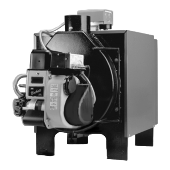
LEDV SERIES DIRECT VENT
As an ENERGY STAR Partner, Burnham Corporation has determined that the LEDV-1, fired at the 0.60 GPH rate,
meets the ENERGY STAR guidelines for Energy efficiency established by the United States Environmental Protection
Agency (EPA).
For service or repairs to boiler, call your heating contractor. When seeking information on boiler, provide
Boiler Model Number and Serial Number as shown on Rating Label.
Boiler Model Number
LEDV__ - _______
Heating Contractor
Address
81433101R3-3/00
OIL FIRED BOILER
Boiler Serial Number
6 _ _ _ _ _ _ _
Installation Date
Phone Number
1
Price - $3.00
Advertisement
Table of Contents

Related Manuals for Burnham LEDV SERIES


Summary of Contents for Burnham LEDV SERIES
- Page 1 LEDV SERIES DIRECT VENT OIL FIRED BOILER As an ENERGY STAR Partner, Burnham Corporation has determined that the LEDV-1, fired at the 0.60 GPH rate, meets the ENERGY STAR guidelines for Energy efficiency established by the United States Environmental Protection Agency (EPA).
- Page 2 It is the responsibility of the installing contractor to see that all controls are correctly installed and are operating properly when the installation is completed.
- Page 3 (i. e. wood, coal) or gaseous fuel (i. e. natural gas, LP/propane). All flammable debris, rags, paper, wood scraps, etc., should be kept clear of the boiler at all times. Keep the boiler area clean and free of fire hazards.
- Page 4 A. Current Edition of Canadian Standards Association CSA B139, "Installation Code for Oil B urning Equipment", for recommended Installation Practices. This boiler is suitable for installation on combustible flooring. Boiler cannot be installed on carpeting. F o r o p ti mu m p e r f o rm a n c e a nd s e rv i c e a b ilit y f r om th is u nit adh e r e t o t h e f o ll o w in g recommendations: Do not tamper w ith or alter the unit or controls.
-
Page 5: Table Of Contents
Water Piping and Trim ... 9 Venting/Air Intake Piping ... 12 Electrical and Sequence of Operations .. 18 Oil Piping ... 20 VII. System Start-up ... 22 VIII. Service and Cleaning ... 26 Repair Parts ... 29 Figure 1: LEDV Packaged Boiler... -
Page 6: I. Pre-Installation
1. ALL EQUIPMENT is carefully manufactured, inspected and packed. Our responsibility ceases upon delivery of crated boiler to the carrier in good condition. 2. ANY CLAIMS for damage or shortage in shipment must be filed immediately against the carrier by the consignee. -
Page 7: Ii. Unpack Boiler
. REMOVAL OF BOILER FROM SKID 1. Boiler is secured to base with 2 bolts, 1 at left front and 1 at right rear. Remove both bolts. 2. Tilt boiler, "walk" boiler backward, and set rear legs down on floor. - Page 8 TS-98-14-A Figure 3: Proper Hinge Bracket Installation Figure 4: Hinge Assembly Figure 2: Minimum Clearances to Combustible Materials...
-
Page 9: Iii. Water Piping And Trim
Refer to the Alliance Installation, Operating, and Service Instructions for additional information. 4. Use a system bypass if the boiler is to be operated in a system which has a large volume or excessive radiation where low boiler water temperatures may be encountered (i.e. - Page 10 . After the boiler and system have been cleaned and flushed, and before refilling the entire system add appropriate water treatment chemicals, if necessary, to bring the pH between 7 and 11.
- Page 11 Figure 6: Recommended Piping for Combination Heating & Cooling (Refrigeration) Systems Figure 7: Recommended Boiler Piping for Zoning with Circulators...
-
Page 12: Iv. Venting/Air Intake Piping
Contact local building or fire officials about restrictions and installation inspection in your area. 2. The LEDV Series is designed as a Direct Vent boiler. In this configuration, all air for combustion is supplied directly to the burner from outdoors and flue gases are vented directly outdoors (through wall). - Page 13 10 Ft. 15 Ft. 20 Ft. 8. The vent system must be completed with the Direct Oil™ Vent Kit, which is shipped with the boiler. Vent Installation (Direct Vent and Side-Wall Vent) 1. Install Vent Terminal. See Figure 10. 8113302...
- Page 14 Figure 10: Vent Installation Figure 11: Vent Connector, Un-Assembled...
- Page 15 Figure 12: Vent Connector, Assembled Figure 13: Air Intake Installation...
- Page 16 Apply a continuous bead of high temperature adhesive/sealant (supplied with boiler) to inside of appliance adapter (approximately ½ inch from end). b. Slip appliance adapter over boiler flue collar and tighten gear clamp. 5. Connect vent pipe to terminal. a. Carefully slide insulation sleeve over vent connector and vent pipe until gear clamp on small end of connector can be accessed.
- Page 17 6. Install air intake terminal. See Figure 13. 7. Seal all external joints with weatherproof caulk. Air Intake Installation (Indoor Air for Combustion) 1. Remove the black plastic inlet cover from the right side of the Beckett AFII burner. 2. Attach the Air Intake Terminal directly to the burner intake collar.
-
Page 18: V. Electrical And Sequence Of Operations
(2) minutes. 4. CAD Cell. The Beckett AFII burners used on the LEDV Series are supplied with a C554A Cadmium Sulfide (cad cell) Flame Detector to monitor the burner flame and shut down the burner on ignition failure or on flame failure during the run cycle. - Page 19 Figure 15: Schematic Wiring Diagram...
-
Page 20: Vi. Oil Piping
VI. Oil Piping General 1. Use flexible oil line(s) so that Swing Door can be opened without disconnecting oil supply. 2. A supply line fuel oil filter is recommended as a minimum for all firing rates but a pleated paper fuel oil filter is recommended for the lowest (.6 GPH) firing rate application to prevent nozzle fouling. - Page 21 . Two-Pipe Oil Lines. 1. For two-pipe systems where more lift is required, the two-stage fuel unit is recommended. Table 2 (single-stage) and Table 3 (two-stage) show allowable lift and lengths of 3/8-inch and ½-inch OD tubing for both suction and return lines. Refer to Figure 17.
-
Page 22: Vii. System Start-Up
Before opening swing door, turn off service switch to boiler to prevent accidental firing of burner outside the combustion chamber. Be sure to tighten swing door fastener completely when service is completed. - Page 23 FUEL LEAKS — Any fuel leak between the d. AIR LEAKS — Any such leaks should be with the microTEKDV boiler is the result of extensive testing to obtain the best flame shape and efficient combustion. Other brands of the...
- Page 24 It chills the flame and causes smoke and unburned fuel to pass out of the combustion chamber and clog the flueways of the boiler. h. COLD OIL — If the oil temperature approaching the fuel pump is 40°F or lower poor combustion or delayed ignition may result.
- Page 25 Both can result in reduced boiler life. The accumulation of sediment can eventually isolate the water from contacting the steel. When this happens the steel in that area gets extremely hot and eventually cracks.
-
Page 26: Viii. Service And Cleaning
Before opening swing door, turn off service switch to boiler to prevent accidental firing of burner outside the combustion chamber. Be sure to tighten swing door fasteners completely when service is completed. - Page 27 Monthly Blowoff. During the heating season, if an external float type low water cutoff is on the boiler, the blow off valve should be opened once a month (use greater frequency where conditions warrant), to flush out the sediment chamber so the device will be free to function properly.
- Page 28 Service Notes...
-
Page 29: Ix. Repair Parts
All LEDV Series Repair Parts may be obtained through your local Burnham Wholesale Distributor. Should you require assistance in locating a Burnham Distributor in your area, or have questions regarding the avail- ability of Burnham products or repair parts, please contact your Burnham Regional Sales Office as listed below. - Page 30 Figure 19: LEDV Boiler Trim & Controls...
- Page 31 Figure 20: LEDV Boiler Jacket & Insulation...
- Page 32 Figure 21: LEDV Bare Boiler Assembly...
- Page 34 Figure 23: Beckett AFII Oil Burner Repair Part For replacement oil burner parts, contact your wholesaler or the burner manufacturer: R.W. Beckett Co., P.O. Box 1289, Elyria, OH 44036 (216) 327-1060 or (800) OIL BURN(645-2876)
- Page 35 BECKETT AFII BURNER REPLACEMENT PARTS Part Description Com plete B urner (without Primary Control) Air Tube Com bination Air Tube Screws Blower Wheel Coupling (Motor to Pump) E lectrodes (Replacement Kit) Escutcheon Plate Stop Sc rew Fuel Line Fuel Pum p (Single Stage, with S olenoid Valve) Fuel Pump (Two Stage, with S olenoid Valve)
Need help?
Do you have a question about the LEDV SERIES and is the answer not in the manual?
Questions and answers