Table of Contents
Advertisement
Quick Links
Advertisement
Table of Contents

Subscribe to Our Youtube Channel
Related Manuals for Cisco Nexus 9396TX


Summary of Contents for Cisco Nexus 9396TX
- Page 1 Cisco Nexus 9396TX NX-OS Mode Switch Hardware Installation Guide First Published: 2014-09-30 Last Modified: 2017-10-05 Americas Headquarters Cisco Systems, Inc. 170 West Tasman Drive San Jose, CA 95134-1706 http://www.cisco.com Tel: 408 526-4000 800 553-NETS (6387) Fax: 408 527-0883...
- Page 2 Cisco and the Cisco logo are trademarks or registered trademarks of Cisco and/or its affiliates in the U.S. and other countries. To view a list of Cisco trademarks, go to this URL: https://www.cisco.com/go/trademarks. Third-party trademarks mentioned are the property of their respective owners. The use of the word partner does not imply a partnership relationship between Cisco and any other company.
-
Page 3: Table Of Contents
Minimizing Electromagnetic and Radio Frequency Interference Shock and Vibration Requirements Grounding Requirements Planning for Power Requirements Airflow Requirements Rack and Cabinet Requirements Clearance Requirements C H A P T E R 3 Installing the Chassis Cisco Nexus 9396TX NX-OS Mode Switch Hardware Installation Guide... - Page 4 Removing an HVAC/HVDC Power Supply Removing a DC Power Supply Installing an AC Power Supply Installing an HVAC/HVDC Power Supply Installing a DC Power Supply Wiring a 48 V DC Electrical Connector Block Cisco Nexus 9396TX NX-OS Mode Switch Hardware Installation Guide...
- Page 5 A P P E N D I X C LEDs Switch Chassis LEDs Uplink Module LEDs Fan Module LEDs Power Supply LEDs A P P E N D I X D Additional Kits Rack Mount Kit N9K-C9300-RMK Cisco Nexus 9396TX NX-OS Mode Switch Hardware Installation Guide...
- Page 6 Contents A P P E N D I X E Site Preparation and Maintenance Records Site Preparation Checklist Contact and Site Information Chassis and Module Information Cisco Nexus 9396TX NX-OS Mode Switch Hardware Installation Guide...
-
Page 7: Preface
Audience, on page vii • Documentation Conventions, on page vii • Related Documentation for Cisco Nexus 9000 Series NX-OS Software, on page viii • Documentation Feedback, on page x • Obtaining Documentation and Submitting a Service Request, on page x... -
Page 8: Related Documentation For Cisco Nexus 9000 Series Nx-Os Software
These guides are available at the following URL: https://www.cisco.com/en/US/products/ps13386/products_installation_and_configuration_guides_list.html The documents in this category include: • Cisco Nexus 2000 Series NX-OS Fabric Extender Software Configuration Guide for Cisco Nexus 9000 Series Switches • Cisco Nexus 9000 Series NX-OS Fundamentals Configuration Guide •... - Page 9 • Cisco Nexus 9000 Series NX-OS VXLAN Configuration Guide Other Software Documents • Cisco Nexus 7000 Series and 9000 Series NX-OS MIB Quick Reference • Cisco Nexus 9000 Series NX-OS Programmability Guide • Cisco Nexus 9000 Series NX-OS Software Upgrade and Downgrade Guide •...
-
Page 10: Documentation Feedback
What's New in Cisco Product Documentation, at: https://www.cisco.com/warp/public/687/Directory/DirTAC.shtml. Subscribe to What's New in Cisco Product Documentation, which lists all new and revised Cisco technical documentation as an RSS feed and delivers content directly to your desktop using a reader application. The RSS feeds are a free service. -
Page 11: Overview
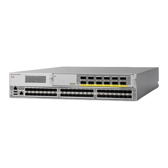
Overview, on page 1 Overview The Cisco Nexus 9396TX switch (N9K-C9396TX) is a 2-RU, fixed-port switch designed for Top-of-Rack (ToR), Middle-of-Rack (MoR), and End-of-Rack (EoR) deployment in data centers. This switch has 48 fixed 1- and 10-GBASE-T downlink ports (supporting 100 Megabit, 1 Gigabit, and 10-Gigabit Ethernet) and a choice of 4-, 6-, or 12-port uplink modules. - Page 12 2.5 W (less than 0.5 A inclusive of surge current). Devices, such as external hard drives, that instantaneously draw more than 0.5 A are not supported. Cisco Nexus 9396TX NX-OS Mode Switch Hardware Installation Guide...
- Page 13 4-post racks (1 bracket on each of 2 Power supply slots are sides). numbered 1 on the left and 2 on the right (as seen when looking at the power supplies). Cisco Nexus 9396TX NX-OS Mode Switch Hardware Installation Guide...
- Page 14 If the switch has port-side exhaust airflow (blue coloring for fan modules), you must locate the ports in the hot aisle. If you locate the air intake in a hot aisle, the switch can overheat and shut down. Cisco Nexus 9396TX NX-OS Mode Switch Hardware Installation Guide...
-
Page 15: Preparing The Site
Altitude Requirements Altitude rating is based on power supply installed; see critical components list in the system CB report for altitude rating. Cisco Nexus 9396TX NX-OS Mode Switch Hardware Installation Guide... -
Page 16: Dust And Particulate Requirements
The wiring is unlikely to emit radio interference if you use a twisted-pair cable with a good distribution of grounding conductors. If you exceed the recommended distances, use a high-quality twisted-pair cable with one ground conductor for each data signal when applicable. Cisco Nexus 9396TX NX-OS Mode Switch Hardware Installation Guide... -
Page 17: Shock And Vibration Requirements
• Two 1200-W HVAC/HVDC power supplies • Two 930-W DC power supplies Note Both power supplies must be the same type. Do not mix AC, DC, and HVAC/HVDC power supplies in the same chassis. Cisco Nexus 9396TX NX-OS Mode Switch Hardware Installation Guide... - Page 18 • Ensure that the protective devices are rated not greater than 30A when the switch is powered with regular DC power supplies (rated 48-60VDC). • Ensure that the protective devices are rated not greater than 10A when the switch is powered with HVDC power supplies (rated 240-350VDC). Cisco Nexus 9396TX NX-OS Mode Switch Hardware Installation Guide...
-
Page 19: Airflow Requirements
The fan and power supply modules must have the same direction of airflow (even if their coloring is different). If you must change the airflow direction for the switch, you must shutdown the switch before changing the modules. Cisco Nexus 9396TX NX-OS Mode Switch Hardware Installation Guide... -
Page 20: Rack And Cabinet Requirements
Provide the chassis with adequate clearance to route cables, provide airflow, and maintain the switch. For the clearances required for an installation of this chassis in a four-post rack, see the following figure. Cisco Nexus 9396TX NX-OS Mode Switch Hardware Installation Guide... - Page 21 Service clearance that is required for replacing the chassis (equals the length of the chassis). Note Both the front and rear of the chassis must be open to both aisles for airflow. Cisco Nexus 9396TX NX-OS Mode Switch Hardware Installation Guide...
- Page 22 Preparing the Site Clearance Requirements Cisco Nexus 9396TX NX-OS Mode Switch Hardware Installation Guide...
-
Page 23: Installation Options With Rack-Mount Kits, Racks, And Cabinets
You can install the switch using the following rack-mount options: • Rack-mount kit (N9K-C9300-RMK) which you can order from Cisco. You can install the switch in the following types of racks: •... -
Page 24: Install A Rack
If you need to move or ship the system in the future, you will need this container. Step 1 Compare the shipment to the equipment list that is provided by your customer service representative and verify that you have received all of the ordered items. Cisco Nexus 9396TX NX-OS Mode Switch Hardware Installation Guide... - Page 25 • Invoice number of the shipper (see the packing slip) • Model and serial number of the missing or damaged unit • Description of the problem and how it affects the installation Cisco Nexus 9396TX NX-OS Mode Switch Hardware Installation Guide...
-
Page 26: Planning How To Position The Chassis In The Rack
Attaching Center-Mount Brackets to the Chassis You need to attach a right-angled bracket to each side of the chassis. This bracket centers the chassis and secures it in place on a two-post rack. Cisco Nexus 9396TX NX-OS Mode Switch Hardware Installation Guide... - Page 27 Use four M4 x 8 mm screws to attach the bracket to the chassis. Tighten each screw to 11 to 15 in-lb (1.2 to 1.7 N·m). Step 3 Repeat Steps 1 and 2 to attach the second center-mount bracket to the other side of the chassis. Cisco Nexus 9396TX NX-OS Mode Switch Hardware Installation Guide...
-
Page 28: Installing The Chassis In A Two-Post Rack
• Make sure that you have six customer-supplied rack-mount screws (typically M6 x 10 mm or the appropriate screw for the vertical mounting rails on the rack). • You have at least two people to install the chassis. Cisco Nexus 9396TX NX-OS Mode Switch Hardware Installation Guide... - Page 29 Tighten each screw to the appropriate torque setting for the screws (for M6 x 10 mm screws, use 40 in-lbs [4.5 N·m] of torque). Cisco Nexus 9396TX NX-OS Mode Switch Hardware Installation Guide...
-
Page 30: Installing The Chassis In A Four-Post Rack
• Verify that you have 8 screws for attaching the bottom support brackets to the racks (typically M6 x 10 mm screws or the screw appropriate for the vertical mounting rails on the rack. Cisco Nexus 9396TX NX-OS Mode Switch Hardware Installation Guide... - Page 31 (typically M6 x 10 mm screws) to secure that portion to the vertical mounting rails on the rack. Tighten each screw to the appropriate torque setting for the screws (for M6 x 10 mm screws, use 40 in. lbs [4.5 N·m] of torque). Cisco Nexus 9396TX NX-OS Mode Switch Hardware Installation Guide...
-
Page 32: Attaching Front-Mount Brackets To The Chassis
You are ready to install two front-mount brackets on the chassis. Attaching Front-Mount Brackets to the Chassis You need to attach a right-angled bracket to each side of the chassis. This bracket holds the chassis in place on a four-post rack. Cisco Nexus 9396TX NX-OS Mode Switch Hardware Installation Guide... -
Page 33: Installing The Chassis In A Four-Post Rack
Warning Statement 1074 Comply with Local and National Electrical Codes To reduce risk of electric shock or fire, installation of the equipment must comply with local and national electrical codes. Cisco Nexus 9396TX NX-OS Mode Switch Hardware Installation Guide... - Page 34 If this happens, press the side rails toward the sides of the chassis so that the chassis stops can go inside the chassis and hold it in place on the rack. Cisco Nexus 9396TX NX-OS Mode Switch Hardware Installation Guide...
-
Page 35: Grounding The Chassis
You can also ground the chassis, which is required if the rack is not grounded, by attaching a customer-supplied grounding cable. Attach the cable to the chassis grounding pad and the facility ground. Cisco Nexus 9396TX NX-OS Mode Switch Hardware Installation Guide... - Page 36 Secure the grounding lug to the chassis grounding pad with two M4 screws, see the previous figure. Tighten the screws to 11 to 15 in-lb (1.24 to 1.69 N·m) of torque. Cisco Nexus 9396TX NX-OS Mode Switch Hardware Installation Guide...
-
Page 37: Starting The Switch
2. Remove the nuts from each of the terminal posts for the power supply. 3. Place the power cable negative-wire terminal ring on the negative terminal for the power source and secure them with a terminal nut. Cisco Nexus 9396TX NX-OS Mode Switch Hardware Installation Guide... - Page 38 A setup utility automatically launches the first time that you access the switch and guides you through the basic configuration. For instructions on how to configure the switch and check module connectivity, see the appropriate Cisco Nexus 9000 Series configuration guide.
-
Page 39: Connecting The Switch To The Network
10 Gbps. If you change the speed, you must also use a QSFP-to-SFP adapter and a supported SFP+ transceiver in each of the converted SFP+ ports. All of the ports in a group of Cisco Nexus 9396TX NX-OS Mode Switch Hardware Installation Guide... -
Page 40: Downlink Connections
Before removing such a transceiver from the switch, remove the cable from the transceiver. To maximize the effectiveness and life of your transceivers and optical cables, do the following: Cisco Nexus 9396TX NX-OS Mode Switch Hardware Installation Guide... - Page 41 Viewing the laser output with certain optical instruments (for example, eye loupes, magnifiers, and microscopes) within a distance of 100 mm may pose an eye hazard. Cisco Nexus 9396TX NX-OS Mode Switch Hardware Installation Guide...
-
Page 42: Maintaining Transceivers And Optical Cables
• Inspect routinely for dust and damage. If you suspect damage, clean and then inspect fiber ends under a microscope to determine if damage has occurred. Cisco Nexus 9396TX NX-OS Mode Switch Hardware Installation Guide... -
Page 43: Replacing Modules
Step 8 Holding the replacement module by its two handles, position the module with the electrical components on its backside facing the open uplink-module slot. Cisco Nexus 9396TX NX-OS Mode Switch Hardware Installation Guide... -
Page 44: Replacing A Fan Module During Operations
If you are not able to push the module all the way into the slot, carefully slide the module out of the slot and Note check its electrical connectors for damage. If damaged, contact Cisco Technical Assistance for help. If undamaged, repeat Step 6 to reinstall the module. - Page 45 Verify that you have the right fan module for the chassis. The correct fan module has one of the following part numbers: • N9K-C9300-FAN2-B (port-side exhaust airflow direction and a blue stripe) • N9K-C9300-FAN2 (port-side intake airflow direction and a burgundy stripe) Cisco Nexus 9396TX NX-OS Mode Switch Hardware Installation Guide...
-
Page 46: Replacing A Power Supply Module
If the STS LED does not turn on, slide the module out of the chassis, and visually check the electrical connectors on the back side of the chassis for damage. If damaged, contact Cisco Technical Assistance for help. If undamaged, repeat the previous step to reinstall the module. -
Page 47: Removing An Hvac/Hvdc Power Supply
Do not touch the electrical connectors on the back side of the module and prevent anything else from coming Caution into contact with and damaging the connectors. What to do next You are ready to install an HVAC/HVDC power supply in the open slot. Cisco Nexus 9396TX NX-OS Mode Switch Hardware Installation Guide... -
Page 48: Removing A Dc Power Supply
If the power supply that you are replacing has a different color handle than the replacement power supply, verify that it has or will have the same airflow direction as the other modules in the switch. Cisco Nexus 9396TX NX-OS Mode Switch Hardware Installation Guide... -
Page 49: Installing An Hvac/Hvdc Power Supply
• If you are using DC power for the replacement power supply, the circuit breaker for the power feed to the power supply that you are replacing must be turned off. Cisco Nexus 9396TX NX-OS Mode Switch Hardware Installation Guide... -
Page 50: Installing A Dc Power Supply
If you are using n+n power redundancy, there must be a separate power source for each power supply installed in the chassis (do not mix AC and DC power sources for the same switch). Otherwise, only one power source is required. Cisco Nexus 9396TX NX-OS Mode Switch Hardware Installation Guide... -
Page 51: Wiring A 48 V Dc Electrical Connector Block
This equipment must be grounded. To reduce the risk of electric shock, never defeat the ground conductor or operate the equipment in the absence of a suitably installed ground conductor. Contact the appropriate electrical inspection authority or an electrician if you are uncertain that suitable grounding is available. Cisco Nexus 9396TX NX-OS Mode Switch Hardware Installation Guide... - Page 52 "+ DC". Step 9 Verify that the other ends of the cables are attached to the DC power source and ground. You are then ready to turn on the DC power source. Cisco Nexus 9396TX NX-OS Mode Switch Hardware Installation Guide...
-
Page 53: Rack Specifications
• Standard 19-inch (48.3 cm) (two- or four-post EIA cabinet or rack, with mounting rails that conform to English universal hole spacing per section 1 of ANSI/EIA-310-D-1992). For more information, see Requirements Specific to Perforated Cabinets, on page Cisco Nexus 9396TX NX-OS Mode Switch Hardware Installation Guide... -
Page 54: Requirements Specific To Standard Open Racks
To help with cable management, you might want to allow additional space in the rack above and below the chassis to make it easier to route all of the fiber optic or copper cables through the rack. Cisco Nexus 9396TX NX-OS Mode Switch Hardware Installation Guide... -
Page 55: System Specifications
0 to 13,123 feet (0 to 4,000 meters) Switch Dimensions Switch Width Depth Height Cisco Nexus 9396TX 17.5 inches (44.5 cm) 22.5 inches (57.1 cm) 3.5 inches (8.9 cm) (2 RU) Cisco Nexus 9396TX NX-OS Mode Switch Hardware Installation Guide... -
Page 56: Switch And Module Weights And Quantities
(green) (UCSC-PSU-930WDC) Transceiver and Cable Specifications To determine which transceivers, adapters, and cables are supported by this switch, see https://www.cisco.com/ c/en/us/support/interfaces-modules/transceiver-modules/products-device-support-tables-list.html. To see the transceiver specifications and installation information, see https://www.cisco.com/c/en/us/support/ interfaces-modules/transceiver-modules/products-device-support-tables-list.html. Cisco Nexus 9396TX NX-OS Mode Switch Hardware Installation Guide... -
Page 57: Switch Power Input Requirements
Maximum output power per power supply 650 W Maximum inrush current 33 A (sub-cycle duration) Maximum hold-up time 12 ms at 650 W Power supply output voltage 12 VDC Power supply standby voltage 12 VDC Cisco Nexus 9396TX NX-OS Mode Switch Hardware Installation Guide... -
Page 58: 1200-W Hvac/Hvdc Power Supply Specifications
Specification DC input voltage range Nominal range: -48 to -60 VDC nominal (Range: -40 to -60 VDC) Maximum DC input current 23 A at -48 VDC Maximum input W 1104 W Cisco Nexus 9396TX NX-OS Mode Switch Hardware Installation Guide... -
Page 59: 930-W Dc Power Supply (Port-Side Exhaust) Specifications
The following sections specify the power cables that you can order and use with this switch. AC Power Cables Supported by NX-OS Mode Switches Power Type Power Cord Part Number Cord Set Description CAB-C13-C14-2M Power Cord Jumper, C13-C14 Connectors, 6.6 feet (2.0 m) Cisco Nexus 9396TX NX-OS Mode Switch Hardware Installation Guide... - Page 60 (2.5 m) United Kingdom CAB-9K10A-UK 250 VAC, 10 A, BS1363 plug (13 A fuse), 8.2 (2.5 m) All except Argentina, Brazil, and NO-POWER-CORD No power cord included with Japan switch Cisco Nexus 9396TX NX-OS Mode Switch Hardware Installation Guide...
-
Page 61: Hvac/Hvdc Power Cables Supported By Aci-Mode And Nx-Os Mode Switches
Saf-D-Grid and SD connectors CAB-HVAC-C14-2M HVAC 6.6-foot (2.0 m) cable with Saf-D-Grid and C14 connector (use for up to 240 V) CAB-HVAC-RT-0.6M HVAC 2-foot (0.6 m) cable with Saf-D-Grid and RT connector Cisco Nexus 9396TX NX-OS Mode Switch Hardware Installation Guide... -
Page 62: Dc Power Cable Specifications
The following table lists the regulatory standards compliance for the switch. Table 3: Regulatory Standards Compliance: Safety and EMC Specification Description Regulatory compliance Products should comply with CE Markings according to directives 2004/108/EC and 2006/95/EC. Cisco Nexus 9396TX NX-OS Mode Switch Hardware Installation Guide... - Page 63 • CNS13438 Class A EMC: Immunity • EN55024 • CISPR24 • EN300386 • KN 61000-4 series RoHS The product is RoH-6 compliant with exceptions for leaded-ball grid-array (BGA) balls and lead press-fit connectors. Cisco Nexus 9396TX NX-OS Mode Switch Hardware Installation Guide...
- Page 64 System Specifications System Specifications Cisco Nexus 9396TX NX-OS Mode Switch Hardware Installation Guide...
-
Page 65: Leds
Temperature exceeds the minor alarm threshold. The switch is not receiving power. Green Fans and power supply modules are operational. Amber At least one fan or power supply module is not operating. Cisco Nexus 9396TX NX-OS Mode Switch Hardware Installation Guide... -
Page 66: Uplink Module Leds
The fan module LED is located below the air holes on the front of the module. Color Status Green The fan module is operational. The fan module is not operational (fan is probably not functional). Fan module is not receiving power. Cisco Nexus 9396TX NX-OS Mode Switch Hardware Installation Guide... -
Page 67: Power Supply Leds
Power supply warning—possibly one of the following conditions: • High voltage • High power • Low voltage • Power supply installed in chassis but not connected to a power source • Slow power supply fan Cisco Nexus 9396TX NX-OS Mode Switch Hardware Installation Guide... - Page 68 LEDs Power Supply LEDs Cisco Nexus 9396TX NX-OS Mode Switch Hardware Installation Guide...
-
Page 69: Additional Kits
Rack Mount Kit N9K-C9300-RMK The following table lists and illustrates the contents for the 2-RU rack-mount kit (N9K-C9300-RMK). Illustration Description Quantity Rack-mount kit • Bottom support rails (2) • Front-mount brackets (2) Cisco Nexus 9396TX NX-OS Mode Switch Hardware Installation Guide... - Page 70 Additional Kits Additional Kits Cisco Nexus 9396TX NX-OS Mode Switch Hardware Installation Guide...
- Page 71 Your completion of each task ensures a successful switch installation. Planning Activity Verification Time and Date Space evaluation: Space and layout Floor covering Impact and vibration Lighting Physical access Maintenance access Environmental evaluation: Ambient temperature Humidity Altitude Atmospheric contamination Airflow Cisco Nexus 9396TX NX-OS Mode Switch Hardware Installation Guide...
- Page 72 EMI evaluation: Distance limitations for signaling Site wiring RFI levels Contact and Site Information Use the following worksheet to record contact and site information for the installation. Contact person Contact phone Cisco Nexus 9396TX NX-OS Mode Switch Hardware Installation Guide...
- Page 73 Domain name IP broadcast address Gateway/router address DNS address Use the following worksheet to record information about the modules in the switch. Module Slot Module Type Module Serial Number Notes Uplink module Cisco Nexus 9396TX NX-OS Mode Switch Hardware Installation Guide...
- Page 74 Site Preparation and Maintenance Records Site Preparation and Maintenance Records Module Slot Module Type Module Serial Number Notes Fan module 1 Fan module 2 Fan module 3 Power Supply 1 Power Supply 2 Cisco Nexus 9396TX NX-OS Mode Switch Hardware Installation Guide...
Need help?
Do you have a question about the Nexus 9396TX and is the answer not in the manual?
Questions and answers