Table of Contents
Advertisement
Quick Links
Advertisement
Table of Contents

Related Manuals for SoundMax SM-CCR3037


Summary of Contents for SoundMax SM-CCR3037
- Page 1 SM-CCR3037 USB/SD/MMC media player USB/SD/MMC- Instruction manual...
-
Page 2: Table Of Contents
Dear customer! Thank you for purchasing our product. For safety, it is strongly recommended to read this manual carefully before connecting, operating and/or adjusting the product and keep the manual for reference in the future. Table of contents TABLE OF CONTENTS ......................................2 IMPORTANT SAFEGUARDS ..................................... -
Page 3: Important Safeguards
Important safeguards Read carefully through this manual to familiarize yourself with this high-quality sound system. The beginning of operation is the moment of the unit installation. Before use the device in winter it is recommended to heat up the passenger compartment during 20 seconds or to the operation temperature. Use the unit with the temperature that goes beyond the operation temperature greatly decreases the operation resource of the screen and other components of device and can result an outage. -
Page 4: Accessories
Accessories Receiver 1 pc Front panel 1 pc Carrying case 1 pc ISO connector harness 1 pc Remote controller 1 pc MiniUSB-USB connection cable 1 pc Mounting parts: Hexagon nut M5 T 1 pc Mounting box 1 pc Release keys 2 pcs Metal bar 1 pc... -
Page 5: Installation/Connection
Installation/Connection General notes Choose the mounting location where the unit will not interfere with the normal driving function of the driver. Before finally installing the unit, connect the wiring and make sure that the unit works properly. Consult with your nearest dealer if installation requires the drilling of holes or other modifications of the vehicle. - Page 6 Trim frame installation To install the trim frame, press it to the unit body and push it to fix it in place. This should be done before installing the front panel; otherwise you are not able to install the trim frame. When the trim frame being installed, the side with the groove should face down and fixed first.
- Page 7 Installing the front panel Insert the left side of the panel then, and insert the right side. Close the panel. Press OPEN button to detach the panel. When the front panel is in horizontal position, hold and slide the panel to left and then pull it out.
- Page 8 Connection diagram Notes: In spite of having any kinds of speaker system, must use 4 ohms impedance of speaker to reduce the distortion during high volume level. Prohibit to make the conductors of auto antenna and ground touch with each other.
- Page 9 Using the ISO Connector 1. If your car is equipped with the ISO connector, then connect the ISO connectors as illustrated. 2. For connections without the ISO connectors, check the wiring in the vehicle carefully before connecting, incorrect connection may cause serious damage to this unit. Cut the connector, connect the colored leads of the power cord to the car battery as shown in the colour code table below for speaker and power cable connections.
-
Page 10: Panel Controls
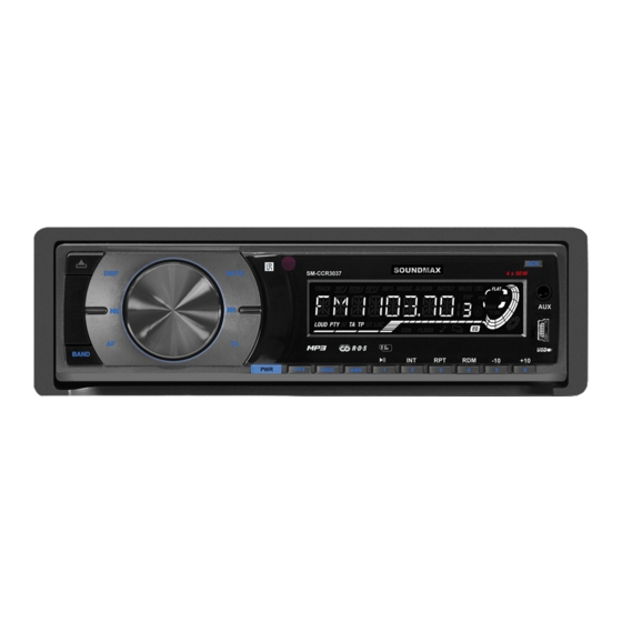
Panel controls Front panel 1. OPEN button 2. PREVIOUS button 3. DISP button 4. SEL button/VOL regulator 5. MUTE button 6. NEXT button 7. IR sensor 8. Display 9. SCN button 10. AUX in jack 11. BAND button 12. AF button 13. - Page 11 Inner panel Press OPEN button on the front panel to detach it. 1. Panel status indicator 2. RESET button (hole) 3. SD/MMC slot Pressing RESET hole will erase the clock setting and stored stations. Panel status indicator lights up when you slide the panel down, flashes when you remove the panel.
- Page 12 Remote controller 1. POWER button 2. PREVIOUS button 3. MUTE button 4. AMS button 5. DISP button 6. MODE button 7. BAND button 8. PLAY/PAUSE/1 button 9. INT/2 button 10. -10/5 button 11. VOL+ button 12. SEL button 13. NEXT button 14.
- Page 13 Changing the battery Pull out the battery tray. Insert the 1 x lithium battery, type CR 2025 3V battery with the stamped (+) mark facing upward. Insert the battery tray into the remote control. Warning: Store the battery where children cannot reach. If a child accidentally swallows the battery, consult a doctor immediately.
-
Page 14: Lcd Layout
LCD layout 1. Track play indicator 2. Album name ON 3. Artist name ON 4. Song name ON 5. Loud function indicator 6. Stereo reception indicator 7. AF function indicator 8. TP function indicator 9. TA function indicator 10. EON function indicator 11. -
Page 15: General Operations
General operations Power button Press PWR button on the panel or POWER button on the RC to switch the unit on. Press and hold this button to switch the unit off. Volume control Rotate VOL regulator on the front panel or press VOL+/VOL- buttons on the RC to adjust volume level. Mute Press MUTE button to mute the sound at once. - Page 16 Clock Press DISP button to switch between clock display and current mode display. Press and hold DISP button; clock will blink. Rotate VOL regulator clockwise or press VOL+ button to set hours; rotate VOL regulator anti- clockwise or press VOL- button to set minutes. Loudness control Press and hold SEL button, then press it repeatedly until LOUD ON is displayed.
-
Page 17: Radio Operations
Radio operations Band selection Press repeatedly BAND button to select your desired radio band in radio mode: FM1, FM2, FM3, MW1 (AM1), MW2 (AM2). Each band can store 6 preset stations, for a total of 30 preset memory stations. Tuning Press and hold PREVIOUS or NEXT button;... -
Page 18: Radio Data System
Radio Data System Note: RDS (Radio Data System) service availability varies with areas. Please understand if RDS service is not available in you area, the following service is not available, either. AF (Alternative Frequencies) function Press AF button to turn the AF function on or off. When the radio signal strength is poor, enabling the AF function will allow the unit to automatically search another station with the same PI (Program Identification) as the current station but with stronger signal strength, so that you do not have to retune the stations when driving between different transmitter coverage... - Page 19 PTY (Program Type) This radio will allow you to select the type of program required, and will search for a station broadcasting that type of program. Press PTY button to show the music type. Then press 1 - 6 number buttons to choose different music programs available.
-
Page 20: Usb/Sd/Mmc Operations
USB/SD/MMC operations MMC/SD card slot Detach the front panel. Carefully insert the SD/MMC card into the card slot on the inner panel. Attach the panel. Unit starts playback automatically. USB port Carefully connect a USB driver to the miniUSB-USB cable included and then insert it into the USB jack on the front panel. - Page 21 Repeat playback When RPT/3 button is pressed, playback of the selected track will be continually repeated until the track repeat mode is cancelled by pressing RPT/3 button again. Random When RDM/4 button is pressed, each track on the storage is played in random instead of normal order. To cancel RANDOM mode, press RDM/4 button again.
-
Page 22: Troubleshooting Guide
Troubleshooting guide Below is a table describing simple measures that can help you eliminate most problems likely to emerge when this unit is in use. If below measures do not help, turn to a service center or to the nearest dealer. Symptom Cause Solution... -
Page 23: Specification
Specification General Power supply 12 V DC Current consumption 10 A Maximum power output 4 x 50 W Dimensions 178 x 50 x 130 mm FM stereo radio Frequency range 65 – 74 MHz / 87.5 - 108.0 MHz Usable sensitivity 12 dBu I.F. - Page 24 ........................................24 ..................................25 ....................................26 ..................................27 ....................................32 ..................................36 ......................................37 ......................................39 (RDS) ................................41 USB/ SD/MMC ..........................43 ........................45 ................................46...
- Page 26 4. ISO miniUSB-USB M5 T (5X25...
- Page 27 « » (...
- Page 28 « » ( – – –...
- Page 29 OPEN,...
- Page 31 ISO, (+)--- (-)--- (+)--- 12 (+)/ (-)--- (+)--- ((-)--- (+)--- (-)---...
- Page 32 OPEN PREVIOUS DISP SEL/ MUTE NEXT BAND PLAY/PAUSE/1 INT/2 RPT/3 RDM/4 -10/5 +10/6 24. USB-...
- Page 33 OPEN, ) RESET SD/MMC RESET...
- Page 34 POWER PREVIOUS MUTE DISP MODE BAND PLAY/PAUSE/1 INT/2 -10/5 VOL+ NEXT VOL- RPT/3 +10/6...
- Page 35 CR 2025 3 – 6...
- Page 36 USB/...
- Page 37 POWER VOL+/VOL-, MUTE, : VOL ( ) => BAS ( ) => TRB ( ) => BAL ( ) => FAD ( VOL+/VOL-, MODE, => USB => => AUX. SEL, LOUD ON (OFF). VOL+/VOL- LOUD ON OFF (...
- Page 38 DISP DISP; VOL+, VOL-, SEL, DSP OFF (DSP ON). VOL+/VOL- : POP M => ROCK M => CLASSICS => FLAT => DSP OFF ( ) RESET ERROR ( MP3-...
- Page 39 BAND, : FM1, FM2, FM3, MW1 (AM1), MW2 (AM2). PREVIOUS NEXT; PREVIOUS NEXT. PREVIOUS/NEXT, AMS; AMS, SEL, STEREO (MONO). VOL+/VOL- (STEREO) (MONO).
- Page 40 SEL, LOCAL (DX). VOL+/VOL- LOCAL ( DX (...
- Page 41 (RDS) RDS ( AF ( RDS. REGION REGION. REG ON (OFF). ON ( OFF ( REG ON ( , PI- REG OFF ( ): PI- TA (...
- Page 42 PTY ( RDS, PTY, 1-6, 1-6,...
- Page 43 USB/ SD/MMC SD/MMC SD/MMC USB- MiniUSB-USB USB/SD/MMC USB: USB 2.0. USB- ID3- MP3- . ID3- NEXT PREVIOUS, -10/5/ +10/6, -10/5 +10/6...
- Page 44 PLAY/PAUSE/1, INT/2, RPT/3, RDM/4,...
- Page 45 “ ”.
- Page 46 12 , 65 – 74 / 87,5 – 108,0 10,7 522 – 1620 USB/SD/MMC – 20 >60 RCA (2 )
Need help?
Do you have a question about the SM-CCR3037 and is the answer not in the manual?
Questions and answers