Table of Contents
Advertisement
Quick Links
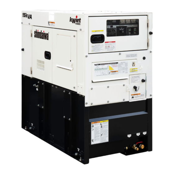
OWNER'S AND OPERATOR'S MANUAL
WARNING
Breathing diesel engine exhaust exposes you to chemicals known to the State of California to
cause cancer and birth defects or other reproductive harm.
Always start and operate the engine in a well ventilated area.
If in an enclosed area, vent the exhaust to the outside.
Do not modify or tamper with the exhaust system.
Do not idle the engine except as necessary.
For more information go to www.P65warnings.ca.gov/diesel.
WARNING
Cancer and reproductive Harm-
www.P65Warnings.ca.gov
WARNING
Batteries, battery posts, terminals and related accessories contain lead and lead compounds, and
other chemicals known to the State of California to cause cancer and birth defects or other
reproductive harm. WASH HANDS AFTER HANDLING.
CAUTION
Do not operate the Generator, or any other appliance, before you have read and understood the
instructions for use and keep near for ready use.
Vertical, Water-Cooled 4-Cycle Diesel Engine
California Proposition 65
DGK15FL
X753-008 31 0
X753801-470 0
Advertisement
Table of Contents

Related Manuals for Shindaiwa DGK15FL


Summary of Contents for Shindaiwa DGK15FL
- Page 1 State of California to cause cancer and birth defects or other reproductive harm. WASH HANDS AFTER HANDLING. CAUTION Do not operate the Generator, or any other appliance, before you have read and understood the instructions for use and keep near for ready use. DGK15FL X753-008 31 0 X753801-470 0...
- Page 3 Introduction Thank you for purchasing this Shindaiwa soundproof diesel engine generator. This manual has been created to ensure safe usage of this generator. Be sure to read this manual before operation. Improper operation/handling of this generator will result in an accident or malfunction.
-
Page 4: Table Of Contents
Table of Contents 1. Safety Instructions ······························································ 2 2. Specifications ····································································· 6 2-1. Specifications ·································································· 6 2-2. Ambient Conditions ·························································· 7 3. Applications ········································································ 7 4. Part Names ········································································· 7 4-1. External View / Part Names ··············································· 7 4-2. Operation Panel Configuration ··········································· 9 5. -
Page 5: Safety Instructions
1. Safety Instructions DANGER : Using a generator indoors CAN KILL YOU IN MINUTES Generator exhaust contains carbon monoxide. This is a poison you cannot see or smell. NEVER use inside a home or garage, EVEN IF doors and windows are open. ... - Page 6 CAUTION : EXPLOSION Never use or recharge the battery if the fluid level is below the minimum level. Do not create sparks or bring flame near the battery as it generates flammable gas. CAUTION : FIRE Do not carry flammable items (such as fuel, gas and paint) or items that are highly combustible near the generator as the muffler, exhaust gas and other parts become extremely hot.
- Page 7 CAUTION : INJURY Always be sure to use “Lifting Hook” when lifting up the generator, and lift slowly and vertically. Personnel performing lifting work must wear protective gear such as helmets, safety shoes and gloves. Remove the wood ties if using anchors to secure the generator. ...
- Page 8 ■ Danger/Warning/Caution Label Locations If danger, warning, or caution labels become damaged and difficult to read, replace with new labels in the indicated locations. Order labels using part number indicated in the parenthesis. ① Warnig/Caution (Part no. :X505-010910) ② Warning: Electric shock (Part no.
-
Page 9: Specifications
2. Specifications 2-1. Specifications Model Unit DGK15FL Generator Type Revolving Field Brushless Rated Frequency Three phase Rated Output(Prime) Single phase 16.5 Three phase 13.2 Standby Output 13.2 Single phase 13.2 Three phase 208/240 Rated Voltage Single phase 120/139/240 Three phase-208V 36.1... -
Page 10: Ambient Conditions
2-2. Ambient Conditions Use this generator in ambient conditions as described below. Failure to provide these conditions can result in problems such as malfunction, insufficient output and reduced durability. ■ Ambient temperature: 5 to 104 °F (-15 to 40 °C) ■... - Page 11 Engine Check Door Fan Guard External Fuel Return External Fuel Inlet Fuel Tank (Inside) Air Cleaner Oil Level Gauge Oil Filler Coolant Sub-Tank Engine Check Door Fuel Filter Alternator Check Door 3way Fuel Valve Oil Filter Battery Spill Containment Oil Drain Plug Water Separator Coolant Drain Plug Wiring Connector...
-
Page 12: Operation Panel Configuration
4-2. Operation Panel Configuration ① ⑪ Circuit Breaker(3-Phase & 1-Phase) Engine Monitor ② ⑫ Voltmeter Available Output Monitor Oil Pressure / Water Temperature ③ ⑬ Ammeter / Speed Selector Switch ④ ⑭ Frequency Meter Display Selector Switch ⑤ ⑮ Pilot Lamp Fuel Level ⑥... -
Page 13: Equipment
5. Equipment 5-1. Three-phase and Single-phase simultaneous Output This generator is capable of generating three-phase and single-phase three-wire output simultaneously. (Three-phase output terminal and single-phase three-wire output terminal are equipped individually.) Neither switching operation of output nor switching operation of wiring is needed. Three-Phase and Single-Phase Three-Wire Output Terminal GROUND <... -
Page 14: Spill Containment
5-3. Spill Containment WARNING : INJURY Do not open the check door when the starter switch is in the AUTO or START position. It will cause injury by rotating parts such as cooling fans and fan belt. Always turn the starter switch to the STOP position and stop the engine, then close and lock OPERATION PANEL DOOR before checking or maintaining the engine or any equipment. -
Page 15: Warning Indicators
5-4. Warning Indicators WARNING : INJURY Do not open the check door when the starter switch is in the AUTO or START position. It will cause injury by rotating parts such as cooling fans and fan belt. Always turn the starter switch to the STOP position and stop the engine, then close and lock OPERATION PANEL DOOR before checking or maintaining the engine or any equipment. - Page 16 < Note > This oil pressure warning indicator cannot detect oil deterioration. Change the engine oil periodically. (Refer to section “8-1. Checking Engine Oil”.) (3) WATER TEMP (Coolant Temperature) Warning Indicator (High Water Temp.) CAUTION: BURNS Do not open the radiator cap immediately after stopping the engine. Do so will result in hot steam gushing out.
-
Page 17: Spill Containment Overflow Warning Indicator
5-5. Spill Containment Overflow Warning Indicator WARNING : INJURY Do not open the check door when the starter switch is in the AUTO or START position. It will cause injury by rotating parts such as cooling fans and fan belt. ... - Page 18 (2) Oil Pressure / Water Temp / Speed Monitor Displays the engine speed, water temperature and oil pressure. Switching the selector switch changes the display in the following order: Speed Water temp Oil press. Engine speed is displayed first, when the engine is started. Oil Press ...
- Page 19 Indicators Check each illuminated warning indicator at the time of automatic stop, and inspect the failed component. (1) Pre-heating Indicator Pilot Lamp The pre-heating indicator illuminates when the starter switch is at START. The pre-heating indicator turns off when pre-heating is completed.
- Page 20 (3) Breaker This switch is for transmitting electrical power to the load side. Turn to ON position to output voltage to the output terminals. Output to the load side is cut off when there is a short circuit or overload on the load side. <...
-
Page 21: Fuel Piping Switch (3Way Fuel Valve)
5-7. Fuel Piping Switch (3Way Fuel Valve) CAUTION : FIRE Always make sure that the engine is stopped when working on piping. Always be sure to wipe up any spilled fuel. After working on the piping, check that there is no fuel leakage. Change the three-way fuel valve to switch to supply fuel from the external tank. -
Page 22: Installation Procedures
(1) Lifting Procedures Always be sure to use lifting hooks when lifting up the generator, and raise it slowly at a completely vertical angle. (2) Transport When transporting this generator, tie rope to the left and right tie downs, and securely fix the generator. <... -
Page 23: Load Connections
Do not place any objects where they will interfere with the radiator or muffler exhaust ports. Objects interfering with these ports will result in reduced engine output, overheating, and electrical component fault/malfunction. Operating the equipment in dusty or excessively salty location can result in a clogged radiator or overheating resulting in malfunction/fault or reduced insulation of electrical components. -
Page 24: Connecting Load Cables
7-2. Connecting Load Cables WARNING : ELECTRIC SHOCK Always turn all the breakers OFF, place the starter switch in the STOP position and stop the engine before connecting/disconnecting the load cable to the output terminal or receptacle. Close the output terminal cover before operating. ... - Page 25 For single-phase load: Terminal voltage is 240 V. GROUND Load Load Load (2) Single-Phase Three-Wire Output Terminal and Receptacle For single-phase three-wire type load: U-W terminal voltage is 240 V. U-N terminal voltage is 120 V. ...
- Page 26 Power available for use by each output terminal and receptacle are as show below. GROUND U-N / W-N / U-W CON1 CON3 CON5 120V Load Load (U-N) CON2 CON4 120V 240V (W-N) (U-W) Load Load Use is possible up to the kVA as shown below. (Unit: kVA) 1-phase 240/120 V 1-phase 120 V receptacle...
-
Page 27: Pre-Operation Inspection
8. Pre-Operation Inspection WARNING : INJURY Always turn the starter switch to the STOP position and stop the engine, then close and lock OPERATION PANEL DOOR before checking or maintaining the engine or any equipment. Do not open the check door when the starter switch is in the AUTO or START position. -
Page 28: Checking Coolant
Relation of Viscosity/Temperature SAE 30 Temp. (°F) SAE 10W-30 SAE 15W-40 (3) Engine Oil Replacement Amount Total Lubrication Oil Amount 0.95 gal. Value in parenthesis is the filter capacity 8-2. Checking Coolant CAUTION: BURNS Do not open the radiator cap immediately after stopping the engine. Do so will result in hot steam gushing out. -
Page 29: Checking The Fuel
Do not mix different brands/types. Doing so could result in a chemical reaction and the creation of toxic substances. Change the LLC every 2 years or 2,000 hours. LLC is a toxic substance. Wear rubber gloves and other protective wear when handling. ... -
Page 30: Checking The Spill Containment
8-4. Checking the Spill Containment CAUTION : FIRE If fuel or oil is leaking, repair the leaking location before operation. Open the check door and check the inside of the spill containment. Flush out any accumulated liquid. Refer to section “10. Inspection/Maintenance (9) Flushing Liquid in Spill Containment”... -
Page 31: Operating Procedures
Replacing the Battery Remove the battery negative (-) cable. (Always be sure to remove the negative (-) side first. ) Remove the battery hold-down clamp. Remove the battery positive (+) cable. Remove the battery. *Reverse the procedure above for installing the battery. (First, connect the positive (+) cable of the replaced battery.) 9. - Page 32 < Note > Check that the surrounding area is safe before starting the engine. When there are multiple workers who are working together, they must mutually signal each other before starting the engine. Do not use in an area with high temperature or humidity, or an area with a large amount of dust.
-
Page 33: Procedures During Operation
(2) Auto Start Use the VOLTAGE REGULATOR dial to adjust the voltage to the specified value. Turn on the three-phase and single-phase breakers on the operation panel of this machine. Set the ACCESSORY switch to OFF position, and use the safety cap to cover it. Confirm that the fuel valves is open. -
Page 34: Stopping Operation
9-3. Stopping Operation CAUTION : BURNS Do not touch the engine and surrounding components immediately after stopping the engine as they are still extremely hot. (1) Manual Start Turn the switches and breakers on the load side to OFF. Turn the three-phase and single-phase breakers on the operation panel to OFF. -
Page 35: Protective Functions
9-4. Protective Functions WARNING : INJURY Do not open the check door when the starter switch is in the AUTO or START position. It will cause injury by rotating parts such as cooling fans and fan belt. Always turn the starter switch to the STOP position and stop the engine, then close and lock OPERATION PANEL DOOR before checking or maintaining the engine or any equipment. -
Page 36: Connecting With External Fuel Tank
9-5. Connecting with External Fuel Tank CAUTION : FIRE Always make sure that the engine is stopped when working on piping. Always be sure to wipe up any spilled fuel. After working on the piping, check that there is no fuel leakage. Inlet Side Inlet Side 3Way Fuel... -
Page 37: Inspection/Maintenance
10. Inspection/Maintenance California Proposition 65 WARNING Batteries, battery posts, terminals and related accessories contain lead and lead compounds, and other chemicals known to the State of California to cause cancer and birth defects or other reproductive harm. WASH HANDS AFTER HANDLING. WARNING : ELECTRIC SHOCK / INJURY ... - Page 38 hazardous materials according to laws and regulations concerning industrial waste. Contact authorized distributor where the generator was purchased if you have any inquiries regarding proper disposal. When check doors are open during maintenance, take measures so that unrelated personnel cannot accidentally come close to the generator.
- Page 39 Every Every Every Every Every Every Every Every Every Description Daily 1,500 2,000 3,000 Remarks hours hours hours hours hours hours hours hours hours Indicators, Gauges Alarms (Check) Insulation test Spill containment fluid (Check/Drain) Spill containment ...
- Page 40 (3) Air Filter Element Cleaning/Replacement Clip Air Cleaner Clean Every 100 hours Replace Once in 6 times cleaning or 1 year Remove the air cleaner clips and cleaner cap. Remove the element. Clean or replace the element. Reverse the procedure Air Cleaner above for re-assembly.
- Page 41 (5) Draining Water from the Fuel Filter/Element Replacement Clean Every 100 hours Replace Every 400 hours Fuel Filter Retainer Place a container under Fuel Filter to catch fuel Ring spilling out of the filter. Close Close the fuel valve. Loosen the retainer ring counterclockwise, and Open Fuel remove the cup and element.
- Page 42 (7) Coolant Replacement Replace Every 1000 hours or 2 years Radiator Plate Filler Neck Set a container to catch spilled coolant. Remove the radiator plate. Remove the radiator cap. Remove the coolant drain plug and packing. After the coolant has been drained, reinsert the coolant drain plug Radiator Cap with new packing.
- Page 43 (9) Rubber Hose and Anti-Vibration Rubber Inspection/Replacement Replace Every 2 years < Note > If the rubber hoses (such as oil, coolant, air and drain) have been hardened or deteriorated, replace them with the new. Request the authorized distributor where the generator was purchased to replace the rubber hose and anti-vibration rubber.
- Page 44 (11) Spill Containment Cleaning/Inspection WARNING : INJURY Always be sure to use “Lifting Hook” when lifting up the generator. Using other parts when lifting up the generator could cause the result of falling. No persons should ever be under a lifted generator. CAUTION : INJURY ...
- Page 45 Check that there no rust has developed inside of the spill containment. If rust has developed, remove the rust and clean again. Tentatively, apply sealant coating to the plug (R1”) or wrap it in seal tape and reinsert it. Allow water to accumulate and check that the spill containment has no internal leakage. Remove the drain plug (R1”) to drain the water.
- Page 46 (12) Elimination of excessive carbon in the exhaust system by extensive light load WARNING : EXHAUST GAS POISONING Do not operate the generator in poorly ventilated areas such as indoors or tunnels, as the exhaust gas of the engine contains substances that are harmful to human health.
-
Page 47: Long-Term Storage
11. Long-Term Storage WARNING : INJURY Always turn the starter switch to the STOP position and stop the engine, then close and lock OPERATION PANEL DOOR before checking or maintaining the engine or any equipment. CAUTION : FIRE Always be sure to wipe up any spilled fuel or oil. ... -
Page 48: Troubleshooting
(2) Double-Stacking Storage Procedures WARNING : INJURY Always be sure to observe the following items when double stacking this generator in a warehouse or similar location. Check that the hood of this generator is not dented, and that bolts are not loose or missing. Set in a location with a flat hard floor capable of withstanding the double- stacking weight. - Page 49 Problem Suspected cause Action Starter motor 1. Battery output is weak 1. Check battery fluid or charge does not drive 2. Battery is deteriorated 2. Replace Battery or speed is low 3. Battery terminal is OFF or loosen 3. Fix/Tighten terminal 4.
- Page 50 Problem Suspected cause Action Overheated 1. Engine thermostat is defective 1.Contact our distributor to repair 2. Water temp sensor is defective 2. Contact our distributor to repair 3. Water temp meter is defective 3. Contact our distributor to repair 4. Fan belt tension is weak 4.
-
Page 51: Generator Circuit Diagram
13. Generator Circuit Diagram... -
Page 52: Engine Electrical Circuit Diagram
14. Engine Electrical Circuit Diagram... - Page 54 ©2020...
Need help?
Do you have a question about the DGK15FL and is the answer not in the manual?
Questions and answers