Table of Contents
Advertisement
Quick Links
OWNER'S AND OPERATOR'S MANUAL
WARNING
Breathing diesel engine exhaust exposes you to chemicals known to the State of California to
cause cancer and birth defects or other reproductive harm.
Always start and operate the engine in a well ventilated area.
If in an enclosed area, vent the exhaust to the outside.
Do not modify or tamper with the exhaust system.
Do not idle the engine except as necessary.
For more information go to www.P65warnings.ca.gov/diesel.
WARNING
Cancer and reproductive Harm-
www.P65Warnings.ca.gov
WARNING
Batteries, battery posts, terminals and related accessories contain lead and lead compounds, and
other chemicals known to the State of California to cause cancer and birth defects or other
reproductive harm. WASH HANDS AFTER HANDLING.
CAUTION
Do not operate the Generator, or any other appliance, before you have read and understood the
instructions for use and keep near for ready use.
Vertical, Water-Cooled 4-Cycle Diesel Engine
California Proposition 65
DGK125F
X753-008 26 0
X753801-430 0
Advertisement
Table of Contents

Related Manuals for Shindaiwa DGK125F


Summary of Contents for Shindaiwa DGK125F
- Page 1 State of California to cause cancer and birth defects or other reproductive harm. WASH HANDS AFTER HANDLING. CAUTION Do not operate the Generator, or any other appliance, before you have read and understood the instructions for use and keep near for ready use. DGK125F X753-008 26 0 X753801-430 0...
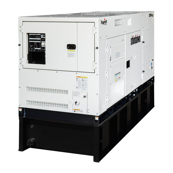
- Page 3 Introduction Thank you for purchasing this Shindaiwa soundproof diesel engine generator. This manual has been created to ensure safe usage of this generator. Be sure to read this manual before operation. Improper operation/handling of this generator will result in an accident or malfunction.
-
Page 4: Table Of Contents
Table of Contents 1. Safety Instructions ····························································· 2 2. Specifications ···································································· 6 2-1. Specifications ································································ 6 2-2. Ambient Conditions ························································· 7 3. Applications ······································································ 7 4. Part Names ········································································ 7 4-1. External View/Part Names ················································ 7 4-2. Operation Panel Configuration ·········································· 11 4-3. -
Page 5: Safety Instructions
1. Safety Instructions WARNING : EXHAUST GAS POISONING Do not operate the generator in poorly ventilated areas such as indoors or tunnels, as the exhaust gas of the engine contains substances that are harmful to human health. Do not direct exhaust fumes at bystanders or buildings. WARNING : ELECTRIC SHOCK ... - Page 6 CAUTION : FIRE Do not carry flammable items (such as fuel, gas and paint) or items that are highly combustible near the generator as the muffler, exhaust gas and other parts become extremely hot. Position this generator 3 ft. (1 m) or more from walls or other hindrances, and on a level surface.
- Page 7 CAUTION : INJURY Always be sure to use Lifting Hook when lifting up the generator, and slowly lift it straight Personnel performing lifting work must wear protective gear such as helmets, safety shoes and gloves. Position the generator on a level stable surface so that it cannot slide or move in any manner.
- Page 8 ■ Warning /Caution Label Locations If warning or caution labels become damaged and difficult to read, replace with new labels in the indicated locations. Order labels using part number indicated in the parenthesis. ① Caution: Do not change voltage Part no. :X505-004620 ②...
-
Page 9: Specifications
2. Specifications 2-1. Specifications Model Unit DGK125F Generator Type Revolving Field Brushless Rated Frequency Three phase Rated Output(Prime) 75[37.5] *1 Single phase 75[37.5] *1 137.5 Three phase Standby Output 82.5 [41.3] *1 Single phase 82.5 [41.3] *1 Three phase 208/240/ [480] *1... -
Page 10: Ambient Conditions
2-2. Ambient Conditions Use this generator in ambient conditions as described below. Failure to provide these conditions can result in problems such as malfunction, insufficient output and reduced durability. ■ Ambient temperature: 5 to 104 °F (-15 to 40 °C) ■... - Page 11 SCR Check Panel Tie Hole Tie hole Inspection / Cleaning Panel DEF Tank Check Panel Tie Hole Engine Fuel Filter Fuel Filter Alternator Fan Guard Turbo Charger Cover Check Door (Main) (Pre) Check Door Electromagnetic Fuel Pump Oil Filter 3way Fuel Valve External Fuel Inlet Oil Level Gauge External Fuel Return...
- Page 12 Coolant Sub-Tank Engine Air Cleaner Check Door Alternator Check Door Radiator Intercooler Fan Guard Battery Coolant Drain Plug Intercooler Drain Plug Fuel Tank (Inside) Output Terminal Terminal Cover Receptacle Cover Remote Start Terminal Receptacle Panel...
- Page 13 Muffler (SCR) Dosing Module Supply Module / Filter SCR Check Panel DEF Tank DEF Tank Check Panel Accessories Owner’s Product Engine Warranty Warranty Operator’s Manual Manual Manual...
-
Page 14: Operation Panel Configuration
4-2. Operation Panel Configuration ① ⑬ Circuit Breaker(3-Phase & 1-Phase) Available Output Monitor ② ⑭ Voltmeter Fuel Level ③ ⑮ Ammeter Fuel Leak Detected Lamp ④ ⑯ Frequency Meter DEF Level ⑤ ⑰ Pilot Lamp Hour Meter ⑥ ⑱ Voltage Regulator Glow Lamp ⑦... -
Page 15: Output Terminal
4-3. Output Terminal Three-Phase Output Terminals Single-Phase Output Terminals 4-4. Receptacle Panel < NOTE > ・All duplex receptacles are GFCI protected and are rated at 20 amps. All twist lock receptacles are rated at 50 amps. ① Single-Phase Circuit Breaker (50A) Single-Phase Circuit Breaker (20A) ②... -
Page 16: Equipment
5. Equipment 5-1. Three-phase and Single-phase simultaneous Output This generator is capable of generating three-phase and single-phase three-wire output simultaneously. (Three-phase output terminal and single-phase three-wire output terminal are equipped individually.) Neither switching operation of output nor switching operation of wiring is needed. Three-Phase and Single-Phase Three-Wire Output Terminal <... -
Page 17: Spill Containment
5-3. Spill Containment WARNING : INJURY Do not open the check door when the starter switch is in the AUTO or START position. It will cause injury by rotating parts such as cooling fans and fan belt. Always turn the starter switch to the STOP position and stop the engine, then close and lock OPERATION PANEL DOOR before checking or maintaining the engine or any equipment. -
Page 18: Warning Indicators
5-4. Warning Indicators WARNING : INJURY Do not open the check door when the starter switch is in the AUTO or START position. It will cause injury by rotating parts such as cooling fans and fan belt. Always turn the starter switch to the STOP position and stop the engine, then close and lock OPERATION PANEL DOOR before checking or maintaining the engine or any equipment. - Page 19 (3) WATER TEMP (Coolant Temperature) Warning Indicator (High Water Temp.) CAUTION: BURNS Do not open the radiator cap immediately after stopping the engine.Do so will result in hot steam gushing out. Hot steam gushes out from the coolant sub-tank if the generator overheats. Do not touch the coolant sub-tank.
-
Page 20: Scr (Selective Catalytic Reduction) System And Indicators
(7) SPILL CONTAINMENT (Spill Containment Amount) Overflow Warning Indicator If the liquid stored in the spill containment exceeds approximately about 41 gal. (155 liters) during operation, the SPILL CONTAINMENT overflow warning indicator illuminates, and the engine automatically stops. If this occurs, flush the liquid stored in the spill containment. - Page 21 Use DEF that is compliant with the ISO (International Organization for Standardization) 22241 standard defined for AUS 32, or the API (American Petroleum Institute) standards. Ⓡ DEF, or other similar urea fluids, may be called AdBlue depending on region. Ⓡ...
- Page 22 PERIODIC PURGE Purge runs automatically after certain period of operating time. PERIODIC PURGE is lit during operation. FORCE PURGE Purge forcibly runs in case that PERIODIC PURGE fails twice. FORCE PURGE is lit during operation. < Note > ...
-
Page 23: Meters And Gauges
■ DEF Indicator Lamp Action LAMP EXH. NO POWER ESCAPE ENGINE (SHUTDOWN) State SYSTEM MODE ○ ○ ○ Stage-Ⅰ - - Warning (Turn ON) (Turn ON) (Turn ON) ○ ○ ○ Stage-Ⅱ - - Early Inducement (Slow Blinking) (Turn ON) (Turn ON) Stage-Ⅲ... - Page 24 (2) Oil Pressure / Water Temp / Speed Monitor Displays the engine speed, water temperature and oil pressure. Switching the selector switch changes the display in the following order: Speed Water temp Oil press. Engine speed is displayed first when the engine is started. Oil Press ...
- Page 25 * Check that 208 V is displayed during operation if using at the three-phase 208 V setting. Check that 480 V is displayed during operation if using at the three-phase 480 V setting. The voltage of single-phase three-wire output of “U-W Voltage” is a value that is one half of the displayed voltage meter value.
- Page 26 < Note > Set the STARTER SWITCH selector to STOP to activate this function. Do not leave the ACCESSORY switch at ON position. This is causing battery from drain out. (3) Breaker This switch is for transmitting electrical power to the load side. Turn to ON position to output voltage to the output terminals.
-
Page 27: Fuel Piping Switch (3Way Fuel Valve)
5-7. Fuel Piping Switch (3Way Fuel Valve) CAUTION : FIRE Always make sure that the engine is stopped when working on piping. Always be sure to wipe up any spilled fuel. After working on the piping, check that there is no fuel leakage. Change the three-way fuel valve to switch to supply fuel from the external tank. -
Page 28: Transport/Installation
6. Transport/Installation 6-1. Transport Procedures WARNING : INJURY Always be sure to use “Lifting Hook” when lifting up the generator. Using other parts when lifting up the generator could cause the result of falling. No persons should ever be under a lifted generator. CAUTION : INJURY ... -
Page 29: Load Connections
If installing this generator, set up barriers or fencing completely around the boundary line of the construction area and take measures to prevent persons not involved in the construction from entering the area. Position this generator on a hard, flat and leveled surface. ... -
Page 30: Connecting Load Cables
(Ex.) If used voltage is 208 V and voltage drops by 10.4 V. Three-phase: Cabtyre cables (Unit: AWG) Length 100 ft. (30 m) 200 ft. 300 ft. 400 ft. 500 ft. 600 ft. or less (61 m) (91 m) (122 m) (152 m) (183 m) Current... - Page 31 If using three-phase output simultaneously with a single-phase three-wire type output, use in a range where the total current does not exceed the rated current. If using three-phase output simultaneously with a single-phase three-wire type output, be careful as it is possible for the outputs to mutually affect each other. ...
- Page 32 (2) Single-Phase Three-Wire Output Terminal and Receptacle For single-phase three-wire type load: U-W terminal voltage is 240 V. U-N terminal voltage is 120 V. W-N terminal voltage is 120 V. For single-phase 240 V load: ...
- Page 33 Power available for use by each output terminal and receptacle are as shown below. Use is possible up to the kVA as shown below. (Unit: kVA) 1-phase 240/120 V 1-phase 120 V receptacle 1-phase, 3-wire receptacle Total output terminal CON1 CON2 CON3...
-
Page 34: Pre-Operation Inspection
8. Pre-Operation Inspection WARNING : INJURY Do not open the check door when the starter switch is in the AUTO or START position. It will cause injury by rotating parts such as cooling fans and fan belt. Always turn the starter switch to the STOP position and stop the engine, then close and lock OPERATION PANEL DOOR before checking or maintaining the engine or any equipment. -
Page 35: Checking Coolant
Relation of Viscosity/Temperature Temp. (°F) SAE 10W-30 SAE 10W-40 SAE 15W-40 (3) Engine Oil Replacement Amount Total Lubrication Oil Amount 6.2 gal. Value in parenthesis is the filter capacity 8-2. Checking Coolant CAUTION: BURNS Do not open the radiator cap immediately after stopping the engine.Do so will result in hot steam gushing out. -
Page 36: Checking The Fan Belt
Change the LLC every 1,000 hours or every year. LLC is a toxic substance. Wear rubber gloves and other protective wear when handling. If someone mistakenly ingests LLC, induce vomiting immediately and seek medical care. If LLC gets on skin or clothing, wash with water immediately. ... -
Page 37: Checking The Fuel
8-4. Checking the Fuel CAUTION : FIRE This generator uses diesel fuel. Always be sure to stop the engine and not bring flames close when inspecting fuel or refueling. Wait until the engine has cooled before performing such procedures. ... -
Page 38: Checking The Spill Containment
DEF may cause inflammation in rare circumstances depending on its constitution. In such cases, take the following actions. In the case of contact with skin, wash off with water. Failure to do so may result in irritation for those with sensitive skin. ... - Page 39 < Note > It is necessary to recharge the battery when the specific gravity of the battery fluid is 1.22 or less. Request the authorized distributor where the generator was purchased to recharge the battery. Fill up battery fluid uintil bottom of sleeve tip under the pouring port, which can be confirmed removing the filler cap.
-
Page 40: Operating Procedures
9. Operating Procedures 9-1. Initial Startup/Pre-Check WARNING : EXHAUST GAS POISONING Do not operate the generator in poorly ventilated areas such as indoors or tunnels, as the exhaust gas of the engine contains substances that are harmful to human health. ... - Page 41 (1) Manual Start Accessory 3-Phase 1-Phase Turn off the three-phase and single-phase Switch Breaker Breaker breakers on the operation panel of this machine. Turn the Throttle switch to IDLING. Set the ACCESSORY switch to OFF, and use the safety cap to cover it. Voltage Regulator Set the STARTER SWITCH selector to START position.
-
Page 42: 208/240/480V Switching Selection
9-2. 208/240/480V Switching Selection WARNING : ELECTRIC SHOCK If performing any electric voltage switching, turn all breakers to OFF and stop operation. Lock the generator using a padlock so that no one except for designated operators can operate switches. CAUTION : PROPERTY DAMAGE ... - Page 43 (2) Adjustment during Operation During load operation, check the voltmeter and finely adjust voltage using the voltage regulator dial. Bleeding air from the fuel system when the engine stops due to running out of fuel. Add fuel to the generator. Air Bleeder Plug Set the ACCESSORY switch ON, activate the electromagnetic pump.Please do not start the...
-
Page 44: Stopping Operation
9-4. Stopping Operation CAUTION : BURNS Do not touch the engine and surrounding components immediately after stopping the engine as they are still extremely hot. (1) Manual Stop Turn the switches and breakers on the load side to OFF. Turn the three-phase and single-phase breakers on the operation panel to OFF. -
Page 45: Protective Functions
9-5. Protective Functions WARNING : INJURY Do not open the check door when the starter switch is in the AUTO or START position. It will cause injury by rotating parts such as cooling fans and fan belt. Always turn the starter switch to the STOP position and stop the engine, then close and lock OPERATION PANEL DOOR before checking or maintaining the engine or any equipment. -
Page 46: Connecting With External Fuel Tank
9-6. Connecting with External Fuel Tank CAUTION : FIRE Always make sure that the engine is stopped when working on piping. Always be sure to wipe up any spilled fuel. After working on the piping, check that there is no fuel leakage. ■Capacity of the external tank should be less than 230 gal. -
Page 47: Inspection/Maintenance
10. Inspection/Maintenance California Proposition 65 WARNING Batteries, battery posts, terminals and related accessories contain lead and lead compounds, and other chemicals known to the State of California to cause cancer and birth defects or other reproductive harm. WASH HANDS AFTER HANDLING. WARNING : ELECTRIC SHOCK / INJURY ... - Page 48 < Note > All procedures except for pre-operation inspection should be performed by specialized technicians. Request authorized distributor where the generator was purchased to perform the procedures in the table with a “”. Always be sure to use genuine parts or those indicated specifically for replacement parts. ...
- Page 49 Every Every Every Every Every Every Description Daily Remarks 250 hrs 500 hrs 750 hrs 1,000 hrs 3,000 hrs 4,500 hrs Fuel/Coolant/Oil Hoses and Anti-Vibration Every Rubber (Replace) 2 years Air Hose(Engine/ Intercooler/Air Creaner) Every SCR system LLC hose 2 years...
- Page 50 (1) Engine Oil Replacement Oil Level Gauge Replace Every 500 hours Oil Filler Set a container to catch spilled engine oil. Remove the oil filler cap. After removing the oil drain plug and o-ring, open the oil drain valve and drain the engine oil. Oil Drain Valve After the oil has been drained,close the oil drain valve and reinsert the oil drain plug with o-ring.
- Page 51 (3) Air Filter Element Cleaning/Replacement Clean (Outer element) Every 250 hours Air Cleaner Replace (Inner / Outer element) Every 500 hours Remove the air cleaner clips and cleaner cap. Remove the outer element. Clean or replace the outer element. Replace by Clip performing the above procedures in reverse order.
- Page 52 < Note > After drainage, start the engine and check that there is no fuel leakage. When the water is accumulate in the cup, drain water from the fuel tank. Be careful not to over-tighten the drain plug and air bleeder plug. ...
- Page 53 Drain plug tightening torque 2 - 3 N・m Air bleeding plug tightening torque 7.9 - 11.7 N・m Outer case tightening torque 28 - 32 N・m < Note > When attaching the cup, check that there is no foreign material adhering to the O-ring. ...
- Page 54 (8) Engine Supply Pump Strainer Cleaning/Replacement Clean/Replace Every 500 hours Place a container under Suppuly Pump to catch spilled fuel. joint Remove the bolt. Clean the strainer with the compressed air and rinse it in the fuel oil and reinstall in the reverse order. Joint bolt tightening torque 14.6 - 24.6 N・m <...
- Page 55 Always be sure to wipe up any spilled DEF. The SCR continues to operate for approximately 3 minutes even after the starter switch is set to the “OFF” position. Wait for 3 minutes or more until the supply module stops operating. ...
- Page 56 (12) Bleeding air from EGR cooler Bleeding air Every after coolant change Loosen the air bleeder plug of the EGR cooler Air Bleeder Plug in order to bleed air from within the EGR and improve cooling performance. When coolant flows out from the air bleeder plug, tighten the air bleeder plug.
- Page 57 (15) Elimination of excessive carbon in the exhaust system by extensive light load WARNING : EXHAUST GAS POISONING Do not operate the generator in poorly ventilated areas such as indoors or tunnels, as the exhaust gas of the engine contains substances that are harmful to human health. ...
- Page 58 (16) Cleaning the Rear Cover CAUTION : BURNS Do not touch the SCR system and surrounding components immediately after stopping the engine as they are still extremely hot. CAUTION : INJURY Position the generator on a level stable surface so that it cannot slide or move in any manner.
-
Page 59: Long-Term Storage
11. Long-Term Storage WARNING : INJURY Always turn the starter switch to the STOP position and stop the engine, then close and lock OPERATION PANEL DOOR before checking or maintaining the engine or any equipment. CAUTION : FIRE Always be sure to wipe up any spilled fuel or oil. ... -
Page 60: Troubleshooting
(2) Double-Stacking Storage Procedures WARNING : INJURY Always be sure to observe the following items when double stacking this generator in a warehouse or similar location. Check that the hood of this generator is not dented, and that bolts are not loose or missing. ... - Page 61 Problem Suspected cause Action Starter motor 1. Battery output is weak 1. Check battery fluid or charge won’t crank 2. Battery is deteriorated 2. Replace Battery or speed is low 3. Battery terminal is OFF or loose 3. Fix/Tighten terminal 4.
- Page 62 Problem Suspected cause Action White smoke 1. Too much or too little oil to cylinder 1. Contact distributor or dealer for repair comes out from 2. Water is interfused in fuel line 2. Drain water in fuel filter or fuel tank Muffler 3.
-
Page 63: Generator Circuit Diagram
13. Generator Circuit Diagram... -
Page 64: Engine Electrical Circuit Diagram
14. Engine Electrical Circuit Diagram... - Page 68 ©2020...
Need help?
Do you have a question about the DGK125F and is the answer not in the manual?
Questions and answers