Table of Contents
Advertisement
Quick Links
OWNER'S AND OPERATOR'S MANUAL
WARNING
Breathing diesel engine exhaust exposes you to chemicals known to the State of California to
cause cancer and birth defects or other reproductive harm.
Always start and operate the engine in a well ventilated area.
If in an enclosed area, vent the exhaust to the outside.
Do not modify or tamper with the exhaust system.
Do not idle the engine except as necessary.
For more information go to www.P65warnings.ca.gov/diesel.
WARNING
Cancer and reproductive Harm-
www.P65Warnings.ca.gov
WARNING
Batteries, battery posts, terminals and related accessories contain lead and lead compounds, and
other chemicals known to the State of California to cause cancer and birth defects or other
reproductive harm. WASH HANDS AFTER HANDLING.
CAUTION
Do not operate the Generator, or any other appliance, before you have read and understood the
instructions for use and keep near for ready use.
Vertical, Water-Cooled 4-Cycle Diesel Engine
California Proposition 65
DGK20FS
X753-008 45 1
X753801-530 2
Advertisement
Table of Contents

Related Manuals for Shindaiwa DGK20FS


Summary of Contents for Shindaiwa DGK20FS
- Page 1 State of California to cause cancer and birth defects or other reproductive harm. WASH HANDS AFTER HANDLING. CAUTION Do not operate the Generator, or any other appliance, before you have read and understood the instructions for use and keep near for ready use. DGK20FS X753-008 45 1 X753801-530 2...
- Page 3 Introduction Thank you for purchasing this Shindaiwa soundproof diesel engine generator. This manual has been created to ensure safe usage of this generator. Be sure to read this manual before operation. Improper operation/handling of this generator will result in an accident or malfunction.
-
Page 4: Table Of Contents
Table of Contents 1. Safety Instructions ······························································ 2 2. Specifications ····································································· 6 2-1. Specifications ·································································· 6 2-2. Ambient Conditions ·························································· 7 3. Applications ········································································ 7 4. Part Names ········································································· 7 4-1. External View / Part Names ··············································· 7 4-2. Operation Panel Configuration ··········································· 9 5. -
Page 5: Safety Instructions
1. Safety Instructions WARNING : EXHAUST GAS POISONING Do not operate the generator in poorly ventilated areas such as indoors or tunnels, as the exhaust gas of the engine contains substances that are harmful to human health. Do not direct exhaust fumes at bystanders or buildings. WARNING : ELECTRIC SHOCK ... - Page 6 CAUTION : EXPLOSION Never use or recharge the battery if the fluid level is below the minimum level. Do not create sparks or bring flame near the battery as it generates flammable gas. CAUTION : FIRE Do not carry flammable items (such as fuel, gas and paint) or items that are highly combustible near the generator as the muffler, exhaust gas and other parts become extremely hot.
- Page 7 CAUTION : INJURY Always be sure to use “Lifting Hook” when lifting up the generator, and lift slowly and vertically. Personnel performing lifting work must wear protective gear such as helmets, safety shoes and gloves. Remove the wood ties if using anchors to secure the generator. ...
- Page 8 ■ Danger/Warning/Caution Label Locations If danger, warning, or caution labels become damaged and difficult to read, replace with new labels in the indicated locations. Order labels using part number indicated in the parenthesis. ① Warnig/Caution (Part no. :X505-007571) ② Warning: Fire (Part no.
-
Page 9: Specifications
2. Specifications 2-1. Specifications Model Unit DGK20FS Generator Type Revolving Field Brushless Rated Frequency Rated Output(Prime) Single phase Standby Output Single phase Rated Voltage Single phase 120/240 Single phase-120V 83.3×2 Rated Current Single phase-240V 83.3 Power Factor Single phase 1.0... -
Page 10: Ambient Conditions
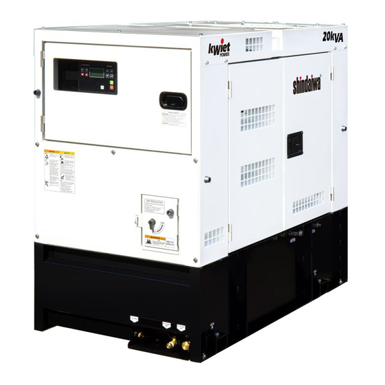
2-2. Ambient Conditions Use this generator in ambient conditions as described below. Failure to provide these conditions can result in problems such as malfunction, insufficient output and reduced durability. ■ Ambient temperature: 5 to 104 °F (-15 to 40 °C) ■... - Page 11 Fan Guard Alternator Check Door Radiator (Inside) Engine Check Door Fuel Filter (Pre) 3way Fuel Valve External Fuel Inlet External Fuel Return Fuel Filter Electromagnetic Fuel Pump (Main) Oil Filler Air Cleaner Coolant Sub-Tank Oil Level Indicator Engine Check Door Alternator Check Door Coolant Drain Plug Battery...
-
Page 12: Operation Panel Configuration
4-2. Operation Panel Configuration ① Circuit Breaker ② Controller ③ Voltage Regulator ④ Power Switch... -
Page 13: Equipment
5. Equipment 5-1. Controller This generator has a Controller which is used for starting or stopping the power generator or the engine, for monitoring. If you turn the Power Switch ON position, the status screen appears.(Refer to section “5-1.Controller (2)Operation Display”.) (1) Front panel elements ①... - Page 14 ⑦ UP button Use this button to move up or increase value. ⑧ PAGE button Use this button to switch over display pages. ⑨ DOWN button Use this button to move down or decrease value. ⑩ ENTER button Use this button finish editing a setpoint or moving right in the history page. ⑪...
- Page 15 Breaker status Not used. RH Running hours. RPM Engine speed. Current process timer Process content and remaining execution time. Measurement Screens ○ Generator Status Screen Contents L1N (V) U-N voltage L2N (V) W-N voltage L1L2 (V) U-W voltage Generator Freq (Hz) Frequency...
-
Page 16: Spill Containment
○ ECU Values Status Screen Contents Load (%) Load factor EngineSpeed (rpm) Engine speed DPFReagen Not used T-coolant (℉) Coolant temperature P-Oil (psi) Oil Pressure FuelRate (g/h) Fuel economy T-IntManifold (℉) Intake temperature in the manifold T-Intake (℉) Intake temperature DEFLevelLamp Not used DEFLevel (%) -
Page 17: Switches
The bed of this generator is equipped with the spill containment (structure for preventing leakage of liquid) so that any spilled liquid will not leak to outside of the generator when oil or fuel is spilled or leak. Before starting operation, check if there is accumulated liquid in the spill containment. -
Page 18: Fuel Piping Switch (3Way Fuel Valve)
(2) Circuit Breakaer This switch is for transmitting electrical power to the load side. Turn to ON position to output voltage to the output terminals. Output to the load side is cut off when there is a short circuit or overload on the load side. <... -
Page 19: Transport/Installation
6. Transport/Installation 6-1. Transport Procedures WARNING : INJURY Always be sure to use “Lifting Hook” when lifting up the generator. Using other parts when lifting up the generator could cause the result of falling. No persons should ever be under a lifted generator. CAUTION : INJURY ... -
Page 20: Load Connections
CAUTION : FIRE Do not carry flammable items (such as fuel, gas and paint) or items that are highly combustible near the generator as the muffler, exhaust gas and other parts become extremely hot. Position this generator 3 ft. (1 m) or more from walls or other hindrances, and on a level surface. -
Page 21: Connecting Load Cables
Load Cable Selection Tables (Ex.) If used voltage is 120 V and voltage drops by 6 V. Single-phase Cabtyre cables (Unit: AWG) Length 200 ft. (61 m) 300 ft. (91 m) 400 ft. (122 m) Current or less 10 A 20 A 30 A 50 A... - Page 22 Single-phase 120V receptacle CON1 Load CON2 Load Power available for use by each output terminal and receptacle are as show below. CON1 Load CON2 Load Maximum individual allowable kVA as shown below. (Unit: kVA) 1-phase 120 V receptacle 1-phase, 3-wireoutput terminal Total CON1...
-
Page 23: Pre-Operation Inspection
< Note > If using a single-phase 120 V (between output terminals U-N/G and W-N/G), connect an equivalent load between U-N/G and W-N/G. If using a single-phase three-wire output terminal simultaneously with a receptacle output, make sure that currents passing through each phase are less than the rated current of this generator. -
Page 24: Checking Coolant
(2) Engine Oil Viscosity Grades Use a diesel engine oil with an appropriate viscosity corresponding to the ambient temperature (refer to the table). Relation of Viscosity/Temperature Temp. (°F) SAE 10W-30 SAE 10W-40 SAE 15W-40 (3) Engine Oil Replacement Amount Total Lubrication Oil Amount 2.7(0.1) gal.... - Page 25 (2) Filling the Radiator Filler Neck Radiator Plate Remove the radiator plate. Remove the radiator cap. Fill with coolant through the filler neck until the radiator is full. Re-attach and tighten the radiator cap. Attach the radiator plate. < Note > ...
-
Page 26: Checking The Fuel
8-3. Checking the Fuel CAUTION : FIRE This generator uses diesel fuel. Always be sure to stop the engine and not bring flames close when inspecting fuel or refueling. Wait until the engine has cooled before performing such procedures. ... -
Page 27: Checking The Spill Containment
(4) Replacing the Fan Belt Request the authorized distributor where the generator was Bolt purchased to replace the fan belt. < Note > Use of a loose or damaged fan belt could result in overheating or insufficient charging. Do not operate the generator if fan guard has been removed. Alternator Bolt 8-5. -
Page 28: Operating Procedures
CAUTION : EXPLOSION Never use or recharge the battery if the fluid level is below the minimum level. Do not create sparks or bring flame near the battery as it generates flammable gas. Check the fluid level, and add distilled water until it reaches the upper level when the fluid level is near the lower level. - Page 29 CAUTION : FIRE Do not carry flammable items (such as fuel, gas and paint) or items that are highly combustible near the generator as the muffler, exhaust gas and other parts become extremely hot. Position this generator 3 ft. (1 m) or more from walls or other hindrances, and on a level surface.
-
Page 30: Procedures During Operation
(1) Manual Start Turn off the Circuit Breaker on the operation panel of this machine. Turn the Power Switch to ON position. Press the Left button or Right button to select MAN mode. Press the Start button to start the engine. Warm up the engine for approximately 5 minutes. -
Page 31: Stopping Operation
(2) Adjustment during Operation During load operation, check the voltmeter and finely adjust voltage using the voltage regulator dial. Restarting after stopping due to running out of fuel The fuel filter includes an automatic air-bleeding device. Restart the engine easily according to the following procedures even if the engine has stopped due to running out of fuel. -
Page 32: Protective Functions
Press the Stop button to shut off the engine. Turn the Power Switch to OFF position. < Note > Set the Power Switch to OFF position if the generator will not be used for a prolonged period. If you leave the Power Switch to ON position, the standby current may drain the battery. (2) Auto Start The engine stops when the REMOTE START terminal opens. - Page 33 Engine Action Breaker Controller Automatic Cause Abnormality Trip Display Shutdown Engine Engine speed is too fast Overspeed (2,070 rpm or more) Spill Containment Spill containment accumulated fluid has Fluid Level exceeded the specified level making it Check necessary to flush the fluid The element is clogged making it necessary...
- Page 34 (2) Low Oil Pressure CAUTION: BURNS Always be sure to stop the engine and allow the engine to cool when performing inspection or maintenance of engine oil. Opening the oil gauge or oil filler cap during operation will result in hot oil gushing out. If the engine oil pressure drops below 14 psi (0.98 x 100 kPa) during operation, the alarm message "ECU P-Oil"...
-
Page 35: Connecting With External Fuel Tank
(6) Air Filter Clogging Up The alarm message “*Wrn Air Filter Clogging Up” will appear if the air cleaner element becomes clogged during operation. If it illuminates, immediately stop the engine and clean or replace the air cleaner element. (Refer to section “10. Inspection/Maintenance (3) Air Filter Element Cleaning/Replacement”.) (7) Fuel Level Low The alarm message “*Wrn Fuel Level”... -
Page 36: Inspection/Maintenance
< Note > If using a hose for the piping, use oil- External Tank resistant hose with an internal diameter of 0.31 to 0.35 in (8 to 9 mm). Set the fuel level of the external fuel tank from 0 to 10 ft. (3 m) above from the bottom of this generator. - Page 37 CAUTION : FIRE Always be sure to wipe up any spilled fuel or oil. CAUTION : BURNS Do not touch the engine and surrounding components immediately after stopping the engine as they are still extremely hot. Do not open the radiator cap immediately after stopping the engine. Do so will result in steam gushing out.
- Page 38 Every Every Every Every Every Every Description Daily Remarks 250 hrs 500 hrs 750 hrs 1,000 hrs 1,500 hrs 3,000 hrs excess water and sediments) Fuel filter (Replace) Fuel tank (Drain water/Clean) (Drain) (Clean) Electromagnetic pump filter ...
- Page 39 Attach the oil filler cap. Open Close < Note > Refer to section “8-1. Checking Engine Oil” for engine oil replacement amounts and types. After reinserting the oil drain plug and shortly after starting the Oil Drain Faucet engine, be sure to always check that there is no oil leakage.
- Page 40 Clear foreign material by pinching the vacuator valve once a week in normal operating conditions or daily if operating in a location that is excessively dirty or dusty. Wipe away any dirt or moisture that has adhered to the parts. Air Filter Element ...
- Page 41 Thread the outer case by hand (do not use a filter wrench), and it in until the O-ring contacts the seal surface, and then tighten it using the special filter wrench. Tighten the drain plug on the bottom and the air-bleeding plug. ■Drain plug tightening torque : 1.5 to 2.5N・m(0.15 to 0.25kgf・m) Air Bleeder...
- Page 42 (7) Draining Water from the Fuel Tank Drain Water Every 250 hours Set a container to catch spilled water. Remove the fuel drain plug and packing (with rubber seal). After the water has been drained, reinsert the fuel drain plug Fuel Drain Plug with new packing (with rubber seal).
- Page 43 (9) Flushing Liquid in Spill Containment Check Daily Set a container to catch spilled liquid from the flushing port of the drain faucet on the front of this generator. Remove the drain plug (R1/2”) and open the drain faucet lever. <...
- Page 44 Spill Containment Separate/Reassemble Turn the 3way fuel valve lever to the “A” side. Remove the wiring connector. Remove the fuel hoses (supply and return sides). Remove the four spill containment fixing bolts (M12, 4 pieces). < Note > When removing the fuel hoses, hold the union joint fixed using a spanner or similar tool. ...
- Page 45 Lifting Hook Lifting Hook Wire Connector Wire Connector Bolt Washer Bolt Position A Washer Position A Bolt Washer Bolt Washer Union Joint Wire Connector Union Joint Wire Connector Fuel Line (Inlet Side) Fuel Line (Inlet Side) Spill Containment Fuel Line (Return Side) Fuel Tank Spill Containment Fuel Line (Return Side)
-
Page 46: Long-Term Storage
CAUTION : FIRE Do not carry flammable items (such as fuel, gas and paint) or items that are highly combustible near the generator as the muffler, exhaust gas and other parts become extremely hot. Position this generator 3 ft. (1 m) or more from walls or other hindrances, and on a level surface. - Page 47 (1) Storage Procedures Perform the following maintenance procedures before storing this generator if it is not going to be used for two months or more. Remove the battery. (Refer to section “8-7. Checking the Battery”.) Replace the engine oil. (Refer to section “10. Inspection/Maintenance (1) Engine Oil Replacement”.) Drain the fuel from the fuel tank and filter.
-
Page 48: Troubleshooting
12. Troubleshooting WARNING : ELECTRIC SHOCK / INJURY Do not touch output terminals or internal electric parts while the generator is operating. Do not open the check door when the power switch is in the ON position. It will cause injury by rotating parts such as cooling fans and fan belt. - Page 49 Problem Suspected cause Action Engine starts but 1. Fuel filter is clogged 1. Clean/Replace fuel filter stalls immediately 2. Water is interfused in fuel line 2. Drain water in water separator, fuel filter or fuel tank 3. Air is interfused in fuel line 3.
- Page 50 Problem Suspected cause Action 1.Battery output is weak 1.Check/ battery liquid/ or Change Controller does not turn on 2.Battery is deteriorated 2.Change battery 3.Battery terminal is OFF or loose 3.Fix/Tighten terminal 4.Battery terminal is corroded 4.Clean terminal 5.Fuse is blown 5.Check/Change fuse 6.Disconnected circuit, loose terminal or 6.Ask our distributor to repair...
-
Page 51: Circuit Diagram
13. Circuit Diagram... - Page 52 ©2022 ©2021...
Need help?
Do you have a question about the DGK20FS and is the answer not in the manual?
Questions and answers