Table of Contents
Advertisement
'
OWNER
S AND OPERATOR
Vertical, Water-Cooled 4-Cycle Diesel Engine
WARNING
Breathing diesel engine exhaust exposes you to chemicals known to the State of
California to cause cancer and birth defects or other reproductive harm.
Always start and operate the engine in a well ventilated area.
If in an enclosed area, vent the exhaust to the outside.
Do not modify or tamper with the exhaust system.
Do not idle the engine except as necessary.
For more information go to www.P65warnings.ca.gov/diesel.
WARNING
Cancer and reproductive Harm-
www.P65Warnings.ca.gov
WARNING
Batteries, battery posts, terminals and related accessories contain lead and lead
compounds, and other chemicals known to the State of California to cause cancer
and birth defects or other reproductive harm. WASH HANDS AFTER HANDLING.
CAUTION
Do not operate the Generator, or any other appliance, before you have read and
understood the instructions for use and keep near for ready use.
California Proposition 65
'
S MANUAL
X753-007 45 0
X753801-230 0
DGK14F
Advertisement
Table of Contents

Subscribe to Our Youtube Channel
Related Manuals for Shindaiwa DGK14F


Summary of Contents for Shindaiwa DGK14F
- Page 1 WASH HANDS AFTER HANDLING. CAUTION Do not operate the Generator, or any other appliance, before you have read and understood the instructions for use and keep near for ready use. DGK14F X753-007 45 0 X753801-230 0...
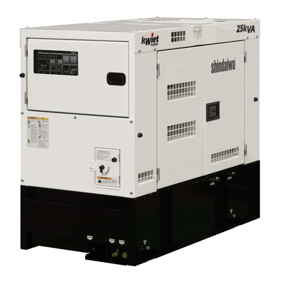
- Page 3 Introduction Thank you for purchasing this Shindaiwa soundproof diesel engine generator. This manual has been created to ensure safe usage of this generator. Be sure to read this manual before operation. Improper operation/handling of this generator will result in an accident or malfunction.
-
Page 4: Table Of Contents
Table of Contents Safety Instructions ................2 Specifications .................. 6 2-1. Specifications ................6 2-2. Ambient Conditions ..............7 Applications ..................7 Part Names ..................7 4-1. External View/Part Names ............7 4-2. Operation Panel Configuration ..........9 Equipment ..................10 5-1. -
Page 5: Safety Instructions
Safety Instructions WARNING : EXHAUST GAS POISONING Do not operate the generator in poorly ventilated areas such as indoors or tunnels, as the exhaust gas of the engine contains substances that are harmful to human health. Do not direct exhaust fumes at bystanders or buildings. WARNING : ELECTRIC SHOCK ... - Page 6 CAUTION : EXPLOSION Never use or recharge the battery if the fluid level is below the minimum level. Do not create sparks or bring flame near the battery as it generates flammable gas. CAUTION : FIRE Do not carry flammable items (such as fuel, gas and paint) or items that are highly combustible near the generator as the muffler, exhaust gas and other parts become extremely hot.
- Page 7 CAUTION : INJURY Always be sure to use lifting hooks when lifting up the generator, and slowly lift it straight up. Personnel performing lifting work must wear protective gears such as helmets, safety shoes and gloves. Remove the wood ties if using anchors to secure the generator. ...
- Page 8 Warning /Caution Label Locations If warning or caution labels become damaged and difficult to read, replace with new labels in the indicated locations. Order labels using part number indicated in the parenthesis. ① Caution: GM SPEC LLC Part no. : X505-007840 ②...
-
Page 9: Specifications
Specifications 2-1. Specifications Model Unit DGK14F Revolving Field Brushless Generator Type Armature Connection ZigZag-W Rated Frequency Rated Output(Prime) 14.7 Standby Output 14.7 Rated Voltage 240/120 Rated Current 58.3 Phase Single phase Power Factor Insulation class Excitation Self Excitation (brushless) No. of Poles... -
Page 10: Ambient Conditions
2-2. Ambient Conditions Use this generator in ambient conditions as described below. Failure to provide these conditions can result in problems such as malfunction, insufficient output and reduced durability. ■ Ambient temperature: 5 to 104 °F (-15 to 40 °C) ■... - Page 11 Fan Guard Radiator * Shown with side-plate removed. Air Cleaner Oil Filler Coolant Sub-Tank Engine Check Door Alternator Check Door Oil Filter Battery Oil Level Gauge Fuel Tank 3way Fuel Valve (Inside) Oil Drain Plug Fuel Filter Water Separator Coolant Drain Plug External Fuel Inlet External Fuel Return Accessories...
-
Page 12: Operation Panel Configuration
4-2. Operation Panel Configuration ⑪ ⑩ ⑨ ⑰ ③ ② ④ ① ⑫ ⑬ ⑭ ⑮ ⑯ ⑤ ⑧ ⑥ ⑦ ○ Main Circuit Breaker Hour Meter ○ Voltmeter Warning Indicators ○ Pilot Lamp Engine Monitor ○ ... -
Page 13: Equipment
Equipment 5-1. Available Output Monitor The available generated output for each output power source is displayed digitally. You can use the display selector switch to change the display in the following order: Total output of 240V Receptacle and 240/120V Receptacle, 120V Receptacles output. Total output of 240V Receptacle and 240/120V Receptacle is always displayed when the engine is started. -
Page 14: Warning Indicators
< Note > Water can also accumulate in the spill containment due to rain entering into the generator. Accordingly, you should periodically flush liquid accumulated within the generator. However, you should flush water according to the frequency/amount of rainfall. ... - Page 15 (2) OIL PRESS (engine oil pressure) Warning Indicator (Low Oil Press.) CAUTION: BURNS Always be sure to stop the engine and allow the engine to cool when performing inspection or maintenance of engine oil. Opening the oil level gauge or oil filler cap during operation will result in hot oil gushing out. If the engine oil pressure drops below 7 psi (0.49 x 100 kPa) during operation, the OIL PRESS warning indicators illuminates, and the engine will be automatically stopped.If this occurs, check the engine oil level and add engine oil until it reaches the maximum level.
-
Page 16: Spill Containment Overflow Warning Indicator
(6) SPILL CONTAINMENT (Spill Containment Amount) Checking Indicator The SPILL CONTAINMENT checking indicator illuminates if the liquid stored in the spill containment exceeds approximately about4.5gal(17 liters) during operation. If it illuminates, immediately stop the engine and flush the liquid stored in the spill containment. (Refer to section “10. - Page 17 Hour Meter ① Speed 時間計 Displays the engine speed. 1800rpm is displayed at 60 Oil Press Water Temp ② Water Temp Displays the temperature of the engine coolant. Speed Normal temperature displayed during operation Fuel Meter should generally between 158°F (70℃) and 203°F (95℃) depending on usage.
- Page 18 (3) Over Crank / No Speed Signal Indicator This indicator illuminates if the engine fails to start. If that happens, set the "STARTER SWITCH" selector to STOP, and inspect the machine. (Refer to section "12. Troubleshooting.") If this indicator starts flashing, the rotation signal has not been detected correctly.Contact the authorized distributor where the Over Crank /No Speed generator was purchased.
-
Page 19: Fuel Piping Switch (3Way Fuel Valve)
5-6. Fuel Piping Switch (3Way Fuel Valve) CAUTION: Always make sure that the engine is stopped when working on piping. Always be sure to wipe up any spilled fuel. After working on the piping, check that there is no fuel leakage. Change the three-way fuel valve to switch to supply fuel from the external tank. -
Page 20: Installation Procedures
(1) Lifting Procedures Always be sure to use lifting hooks when lifting up the generator, and raise it slowly at a completely vertical angle. (2) Transport When transporting this generator, tie rope to the left and right tie downs, and securely fix the generator. -
Page 21: Load Connections
< Note > This generator is manufactured presupposing that it will be installed on a flat, hard and leveled surface. Accordingly, care must be taken as using under any other installation conditions can result in a fault or malfunction. ... -
Page 22: Connecting Load Cables
7-2. Connecting Load Cables WARNING : ELECTRIC SHOCK Always turn all the breakers OFF, place the starter switch in the STOP position and stop the engine before attaching / detaching the load cable to the output terminal or receptacle. ... -
Page 23: Pre-Operation Inspection
8. Pre-Operation Inspection WARNING : INJURY Always turn the starter switch to the STOP position and stop the engine, then close and lock OPERATION PANEL DOOR before checking or maintaining the engine or any equipment. Do not open the check door when the starter switch is in the AUTO or START position. -
Page 24: Checking Coolant
(3) Engine Oil Replacement Amount Total Lubrication Oil Amount 1.9 (0.1) gal. Value in parenthesis is the filter capacity. 8-2. Checking Coolant CAUTION : BURNS Do not open the radiator cap immediately after stopping the engine. Doing so will result in steam gushing out. ... -
Page 25: Checking The Fuel
If LLC gets on skin or clothing, wash with water immediately. LLC is flammable. Store in a location where flame is prohibited and it cannot be accessed by children. Engine coolant could leak if the radiator is not completely tightened or there is a gap in the seating face. -
Page 26: Checking For Fuel, Oil And Coolant Leaks
< Note > The types of liquids that can accumulate in the spill containment include oil, fuel, coolant and battery fluid such that it is not possible to distinguish between rain water and other liquids. Dispose of flushed liquids according to the related laws and regulations. 8-5. -
Page 27: Oprating Procedures
Replacing the Battery Remove the battery negative (-) cable. (Always be sure to remove the negative (-) side first. ) Remove the battery hold-down clamp. Remove the battery positive (+) cable. Remove the battery. * Install the battery by performing the above procedures in the reverse order. (First connect the positive (+) cable of the replaced battery. - Page 28 < Note > Check that the surrounding area is safe before starting the engine. When there are multiple workers who are working together, they must mutually signal each other before starting the engine. Do not use in an area with high temperature or humidity, or an area with a large amount of dust. ...
-
Page 29: Procedures During Operation
(2) Auto Start Use the VOLTAGE REGULATOR dial to adjust the voltage to the specified value. Turn on the main breaker on the operation panel of this machine. Set the ACCESSORY switch to OFF position, and use the safety cap to cover it. Confirm the fuel valves are open. -
Page 30: Stopping Operation
9-3. Stopping Operation CAUTION : BURNS Do not touch the engine and surrounding components immediately after stopping the engine as they are still extremely hot. (1) Manual Start Turn the switches and breakers on the load side to OFF position. Turn off the main breaker on the operation panel of this machine. - Page 31 CAUTION : BURNS Do not touch the engine and surrounding components immediately after stopping the engine as they are still hot. Hot steam gushes out from the coolant sub-tank if the generator overheats. Do not touch the coolant sub-tank. This generator is equipped with functions to automatically stop operation when there is a fault/malfunction during operation, and one to warn the operator of the fault location by use of indicator lamps.
-
Page 32: Connecting With External Fuel Tank
9-5. Connecting with External Fuel Tank CAUTION : FIRE Always make sure that the engine is stopped when working on piping. Always be sure to wipe up any spilled fuel. After working on the piping, check that there is no fuel leakage. Turn the 3way fuel valve lever to the “A”... -
Page 33: Inpection/Maintenance
10. Inpection/Maintenance California Proposition 65 WARNING Batteries, battery posts, terminals and related accessories contain lead and lead compounds, and other chemicals known to the State of California to cause cancer and birth defects or other reproductive harm. WASH HANDS AFTER HANDLING. WARNING : ELECTRIC SHOCK/INJURY ... - Page 34 When check doors are open during maintenance, take measures so that unrelated personnel cannot accidentally come close to the generator. Close all doors and covers if you are going to be away from this generator. Please be careful about a strong wind and the opening and shutting of the door at the sloping place enough.
- Page 35 Every Every Every Every Every Every Every Every Description Daily 100 hrs 200 hrs 400 hrs 450 hrs 500 hrs 800 hrs 1000 hrs 1500 hrs Valve clearance (Check/Adjust) Fuel injector (Check) Elimination of carbon in the exhaust pipe line and muffler Indicators, Gauges...
- Page 36 (2) Replacing the Oil Filter First Time 50 hours Thereafter Every 200 hours Drain the engine oil. (Refer to section “(1) Engine Oil Replacement”.) Remove the oil filter using a filter wrench. Gasket Spread a thin layer of oil on a new oil filter gasket. Thread the oil filter by hand, and turn by hand (do not use a filter wrench) from when the gasket contacts the seal surface until it is securely tightened.
- Page 37 Cleaning the air filter element If dry dust is adhering: Blow compressed air from inside the element. If carbon or oil is adhering: Replace with new parts. (4) Draining Water from the Water Separator Fuel Valve 50 hours First Time Close Every 100 hours Clean...
- Page 38 < Note > When attaching the cup, check that there is no foreign material adhering to the O-ring. After attaching, open the fuel valve, and be sure to always start the engine and check that there is no fuel leakage. ...
- Page 39 (8) Checking the Fan Belt First Time 50 hours Every 100 hours Thereafter ① Fan Belt Tension Press your finger against the middle of the fan belt. (approx. 98N) If the slack is 0.27 to 0.35 inch, the tension is normal. ②...
- Page 40 Drain Valve Drain Valve Drain Valve Lever Loosen Close Fixing Tighten Drain Plug Drain Valve Open Lever Drain Plug(R1/2”) (10) Spill Containment Cleaning/Inspection WARNING : INJURY Do not lift up the unit using tie downs. Use of such could result in the generator falling. ...
- Page 41 Spill Containment Cleaning/Inspection Use a high-pressure cleaner or similar equipment to clean the inside of the spill containment. Remove the drain plug (R1”) to drain the cleaning water. Check that there no rust has developed inside of the spill containment. If rust has developed, remove the rust and clean again.
-
Page 42: Long-Term Storage
(11) Elimination of excessive carbon in the exhaust system by extensive light load WARNING : EXHAUST GAS POISONING Do not operate the generator in poorly ventilated areas such as an indoors or tunnels, as the exhaust gas of the engine contains substances that are harmful to human health. - Page 43 CAUTION : FIRE Always be sure to wipe up any spilled fuel or oil. Allow the generator to cool before covering with the protective cover. CAUTION : BURNS Do not touch the engine and surrounding components immediately after stopping the engine as they are still extremely hot.
-
Page 44: Troubleshooting
12. Troubleshooting WARNING : ELECTRIC SHOCK/INJURY Do not touch output terminals or internal electric parts while the generator is operating. Do not open the check door when the starter switch is in the AUTO or START position. It will cause injury by rotating parts such as cooling fans and fan belt. ... - Page 45 Problem Suspected cause Action Engine starts but 1. Fuel filter is clogged 1. Clean/Replace fuel filter stalls immediately 2. Gauze filter is clogged 2. Clean/Replace gauze filter 3. Water is interfused in fuel line 3. Drain water in water separator, fuel filter or fuel tank 4.
- Page 46 Problem Suspected cause Action The voltage drops 1. AVR is defective 1. Ask our distributor to repair drastically when 2. The current of the used equipment 2. Change to a device with an available connecting to load exceeds the rated current. capacity.
-
Page 47: Generator Circuit Diagram
13. Generator Circuit Diagram... -
Page 48: Engine Electrical Circuit Diagram
14. Engine Electrical Circuit Diagram... - Page 50 ©2019...
Need help?
Do you have a question about the DGK14F and is the answer not in the manual?
Questions and answers