Table of Contents
Advertisement
Quick Links
'
OWNER
S AND OPERATOR
DGK15FU
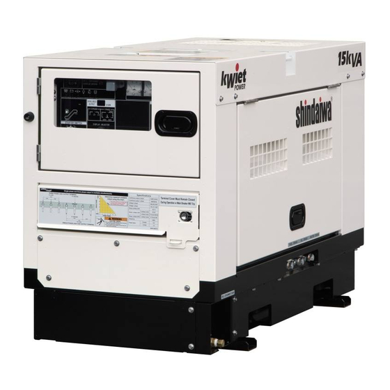
Vertical, Water-Cooled 4-Cycle Diesel Engine
WARNING
Breathing diesel engine exhaust exposes you to chemicals known to the State of
California to cause cancer and birth defects or other reproductive harm.
Always start and operate the engine in a well ventilated area.
If in an enclosed area, vent the exhaust to the outside.
Do not modify or tamper with the exhaust system.
Do not idle the engine except as necessary.
For more information go to www.P65warnings.ca.gov/diesel.
WARNING
Cancer and reproductive Harm-
www.P65Warnings.ca.gov
WARNING
Batteries, battery posts, terminals and related accessories contain lead and lead
compounds, and other chemicals known to the State of California to cause cancer
and birth defects or other reproductive harm. WASH HANDS AFTER HANDLING.
CAUTION
Do not operate the Generator, or any other appliance, before you have read and
understood the instructions for use and keep near for ready use.
California Proposition 65
'
S MANUAL
X753-007 72 0
X753801-250 0
DGK15FU
Advertisement
Table of Contents

Related Manuals for Shindaiwa DGK15FU


Summary of Contents for Shindaiwa DGK15FU
- Page 1 ’ ’ OWNER S AND OPERATOR S MANUAL DGK15FU Vertical, Water-Cooled 4-Cycle Diesel Engine California Proposition 65 WARNING Breathing diesel engine exhaust exposes you to chemicals known to the State of California to cause cancer and birth defects or other reproductive harm.
- Page 3 Introduction Thank you for purchasing this Shindaiwa soundproof diesel engine generator. This manual has been created to ensure safe usage of this generator. Be sure to read this manual before operation. Improper operation/handling of this generator will result in an accident or malfunction.
-
Page 4: Table Of Contents
Table of Contents Safety Instructions ................2 Specifications .................. 6 2-1. Specifications ................6 2-2. Ambient Conditions ..............7 Applications ..................7 Part Names ..................7 4-1. External View/Part Names ............7 4-2. Operation Panel Configuration ..........9 Equipment ..................10 5-1. -
Page 5: Safety Instructions
1. Safety Instructions WARNING : EXHAUST GAS POISONING Do not operate the generator in poorly ventilated areas such as indoors or tunnels, as the exhaust gas of the engine contains substances that are harmful to human health. Do not direct exhaust fumes at bystanders or buildings. WARNING : ELECTRIC SHOCK Do not operate the equipment with any doors or covers open. - Page 6 CAUTION : EXPLOSION Never use or recharge the battery if the fluid level is below the minimum level. Do not create sparks or bring flame near the battery as it generates flammable gas. CAUTION : FIRE Do not carry flammable items (such as fuel, gas and paint) or items that are highly combustible near the generator as the muffler, exhaust gas and other parts become extremely hot.
- Page 7 CAUTION : INJURY Always be sure to use lifting hooks when lifting up the generator, and slowly lift it straight up. Personnel performing lifting work must wear protective gear such as helmets, safety shoes and gloves. Remove the wood ties if using anchors to secure the generator. Position the generator on a level stable surface so that it cannot slide or move in any manner.
- Page 8 Warning /Caution Label Locations If warning or caution labels become damaged and difficult to read, replace with new labels in the indicated locations. Order labels using part number indicated in the parenthesis. ① Terminal Cover Instructions (Part no. : M704-003360) ②...
-
Page 9: Specifications
Specifications 2-1. Specifications Model Unit DGK15FU Revolving Field Brushless Generator Type Rated Frequency Three phase Rated Output(Prime) Single phase 16.5 Three phase 13.2 Standby Output 13.2 Single phase 13.2 Three phase 208/240 Rated Voltage Single phase 120/139/240 Three phase-208V 36.1 Three phase-240V 36.1... -
Page 10: Ambient Conditions
2-2. Ambient Conditions Use this generator in ambient conditions as described below. Failure to provide these conditions can result in problems such as malfunction, insufficient output and reduced durability. ■ Ambient temperature: 5 to 104 °F (-15 to 40 °C) ■... - Page 11 Safety Guard Spill Containment Wiring Connector Check Door Fuel Tank Air Cleaner Oil Level Indicator Coolant Sub-Tank Spill Containment Oil Filter Fuel Filter Spill Containment Drain Valve Battery Coolant Drain Plug Fuel Drain Plug Oil Drain Plug Accessories Owner’s Engine Warranty Operator’s Manual...
-
Page 12: Operation Panel Configuration
4-2. Operation Panel Configuration Spill containment Overflow ① ⑩ Circuit Breaker(3-Phase & 1-Phase) Warning Indicator ② ⑪ Voltmeter Tachometer ③ ⑫ Ammeter Available Output Monitor ④ ⑬ Frequency Meter Display Selector Switch ⑤ ⑭ Pilot Lamp Fuel Meter ⑥ ⑮ Voltage Regulator Hour Meter ⑦... -
Page 13: Equipment
Equipment 5-1. Three-phase and Single-phase simultaneous Output This generator is capable of generating three-phase and single-phase three-wire output simultaneously. (Three-phase output terminal and single-phase three-wire output terminal are equipped individually.) Neither switching operation of output nor switching operation of wiring is needed. Three-Phase and Single-Phase Three-Wire Output Terminal GROUND <... -
Page 14: Warning Indicators
CAUTION : BURNS Do not touch the engine and surrounding components immediately after stopping the engine as they are still extremely hot. The bed of this generator is equipped with a spill containment (structure for preventing leakage of liquid) so that any spilled liquid will not leak to outside of the generator when oil or fuel is spilled or leak. - Page 15 This generator is equipped with the following warning indicators: BATTERY (insufficient charging), OIL PRESS (engine oil pressure), WATER TEMP (coolant temperature), OVER SPEED (engine overspeed) and SPILL CONTAINMENT (spill containment amount). When the engine starts, all the lamps will light off. Moving the starter switch from STOP to START causes the BATTERY and OIL PRESS warning indicator to illuminate, and all of the indicator lights will go off as the engine starts.
-
Page 16: Spill Containment Overflow Warning Indicator
If the coolant temperature rises above 239 °F(115 ℃) during operation, the WATER TEMP warning indicator illuminates, and the engine will be automatically stopped. If this occurs, hot steam will gush out of the coolant sub-tank. Check the coolant sub-tank coolant level after the generator cools and add coolant to the coolant sub-tank if it is insufficient. -
Page 17: Meters And Gauges
If the liquid stored in the spill containment exceeds approximately about 13.7gal. ( 51.7 liters ) during operation, the SPILL CONTAINMENT overflow warning indicator illuminates, and the engine automatically stops. In that case, open the CHECK DOOR and check inside the SPILL CONTAINMENT whether fuel and oil leak. - Page 18 (2) Ammeter Displays the output current (phase current) of the generator. Turn the ammeter selector switch to “L1+U” to display the output current of the three-phase L1 phase and single-phase U phase. Turn the switch to “L3+W” to display the output current of the three-phase L3 phase and single-phase W phase.
- Page 19 Switches Remote Start (1) Starter Switch Terminal The engine warms up and starts automatically. START Pre-Heating 1-Phase The engine starts automatically. Indicator STOP The engine is stopped, and the power supply is turned off completely in this Starter Switch position. You can also operate the accessory switch in this position.
-
Page 20: Transport/Installation
(5) Ammeter Selector Switch This switch is for selecting the output current indicated by the ammeter. Change the switch to display the following output terminal current on the ammeter. Switch Selection “L1+U”: Three-phase L1 phase + Single-phase three-wire U phase (total) ... -
Page 21: Installation Procedures
Lifting Tie-Down Hook < Note > Handle this generator with great care when raising, lowering and transporting. Rough handling of generator can result in damage or malfunction. 6-2. Installation Procedures WARNING : EXHAUST GAS POISONING Do not operate the generator in poorly ventilated areas such as indoors or tunnels, as the exhaust gas of the engine contains substances that are harmful to human health. -
Page 22: Load Connections
Load Connections 7-1. Load Cable Selection CAUTION : PROPERTY DAMAGE Cable burnout could occur due to generated heat if the load current exceeds the allowable current of the cable. The voltage drop between cables is large if the cable is excessively long or thin, resulting in decreased input voltage to equipment using the generator, thereby causing decreased performance, faulty operation and malfunction. -
Page 23: Connecting Load Cables
7-2. Connecting Load Cables WARNING : ELECTRIC SHOCK Before connecting or disconnecting the load cables to/from the output terminal, always turn the output circuit breakers to the OFF position, stop the engine, and remove the starter key. Close the output terminal cover before operating. Do not insert a pin, needle or other metal object into the receptacle. - Page 24 For single-phase load: Terminal voltage is 240 V. GROUND Load Load Load (2) Single-Phase Three-Wire Output Terminal and Receptacle For single-phase three-wire type load: U-W terminal voltage is 240 V. U-N terminal voltage is 120 V. W-N terminal voltage is 120 V. For single-phase 240 V load: For single-phase 120 V load: GROUND...
- Page 25 Power available for use by each output terminal and receptacle are as show below. GROUND U-N / W-N / U-W CON1 CON3 CON5 120V Load Load (U-N) CON2 CON4 120V 240V (W-N) (U-W) Load Load The use is possible up to the kVA as shown below. (Unit: kVA) 1-phase 240/120 V 1-phase 120 V receptacle...
-
Page 26: Pre-Operation Inspection
8. Pre-Operation Inspection WARNING : INJURY Always turn the starter switch to the STOP position and stop the engine, then close and lock OPERATION PANEL DOOR before checking or maintaining the engine or any equipment. Do not open the inspection door when the starter switch is in the AUTO or START position. -
Page 27: Checking Coolant
(1) Types of Engine Oil Use only API service-type CF class. (2) Engine Oil Viscosity Grades Use a diesel engine oil with an appropriate viscosity corresponding to the ambient temperature (refer to the table). Relation of Viscosity/Temperature SAE 30 Temp. -
Page 28: Checking The Fuel
< Note > Use GM SPEC 6277M or equivalent. Use a 50:50 mix of Long Life Coolant (LLC). Always use potable water when mixing the coolant. Use LLC with the same mixture ratio in the coolant sub-tank. Do not increase the LLC mixture ratio unless it is necessary. Doing so could result in overheating or another fault/malfunction. -
Page 29: Checking The Spill Containment
Always be sure to use the fuel filter attached to the fuel inlet. Carefully add fuel until the tank is full. Always be sure to wipe up any spilled fuel. 8-4. Checking the Spill Containment CAUTION : FIRE If fuel or oil is leaking, repair the leaking location before operating. Open the check door and check the inside of the spill containment. -
Page 30: Operating Procedures
Check the fluid level, and add distilled water to the upper level when it is near the lower level. Check the terminals for looseness and tighten if it is too loose. < Note > It is necessary to recharge the battery when the (+) Post (-) Post specific gravity of the battery fluid is 1.23 or less. - Page 31 CAUTION : FIRE Do not carry flammable items (such as fuel, gas and paint) or items that are highly combustible near the generator as the muffler, exhaust gas and other parts become extremely hot. Position this generator 3 ft. (1 m) or more from walls or other hindrances, and on a level surface.
-
Page 32: Procedures During Operation
< Note > The warm-up process starts automatically. Please keep in mind that the muffler may emit some smoke when the engine is started. Never turn accessory switch ON during operation.The engine keeps running while accessory Switch is ON. Use the voltage regulator dial to adjust the voltage to the specified value. 60Hz 240V Turn the breaker on to activate the power supply. -
Page 33: Stopping Operation
Set the STARTER SWITCH selector to "START," and confirm that the engine has started properly. The engine speed is unstable for approximately one minute until the air has been completely pulled out from the fuel line. The engine speed stabilizes once the air is pulled out. -
Page 34: Protective Functions
(2) Auto Start The engine stops when the remote start terminal opens. Set the STARTER SWITCH selector to "STOP," and close the fuel spigot if you do not plan to use the generator for a prolonged period of time. < Note > Never turn accessory switch ON during operation. -
Page 35: Inspection/Maintenance
Protection Feature List Engine Warning Action Breaker Automatic Lamp Cause Abnormality Trip Shutdown Flash Activates due to high water temperature High Water − in the engine Temperature Default 239°F (115℃) Activate due to low oil pressure in the Low Oil −... - Page 36 CAUTION : FIRE Always be sure to wipe up any spilled fuel or oil. CAUTION : BURNS Do not touch the engine and surrounding components immediately after stopping the engine as they are still extremely hot. Do not open the radiator cap immediately after stopping the engine. Doing so will result in steam gushing out.
- Page 37 Inspection Intervals Daily Every Every Inspection Item Every Every Every Inspection 1,000 2,000 hours 100 hours 200 hours 400 hours hours hours Inspect/Add Fuel Inspect/Add Engine Oil 2nd time 1st time Change Engine Oil and after 2nd time 1st time Change Oil Filter...
- Page 38 (1) Engine Oil Replacement First Time 50 hour Oil Filler Thereafter Every 100 hours Oil Level Indicator Set a container to catch spilled engine oil. Remove the oil filler cap. After removing the oil drain plug, drain the engine oil. After the oil has been drained, close and tighten the oil drain plug.
- Page 39 (3) Air Filter Element Cleaning/Replacement 1st Time: 50 hour Clean 2nd Time and after: Every 100 hours Replace Every 400 hours Remove the air cleaner clips and cleaner cap. Remove the element. Clean or replace the element. Reverse the procedure above for re-assembly. Air Cleaner <...
- Page 40 Element part no.: 16271-43561 (Kubota part no.) (5) Draining Water from the Fuel Tank Drain Water Every 200 hours Set a container to catch spilled water. Remove the fuel drain plug and packing. After the water has been drained, tighten the fuel drain plug with new packing.
- Page 41 (7) Fan Belt Adjustment First Time 50 hour Thereafter Every 100 hours Remove the safety guard. Safety Guard Inspect that there is no damage to the fan belt. If so, be sure to replace it. Push the center of the fan belt with your finger (49N “5kg f”), check the slack is about 0.39 in (10mm).
- Page 42 Close the drain valve lever after the liquid has been flushed, and applies sealant coating to the plug or wraps it by seal tape. Drain Valve Drain Valve Lever Drain Valve Lever Drain Valve Loosen Close Close Drain Plug Open (R1/2) Tighten Drain Plug(R1/2)
- Page 43 Spill Containment Cleaning/Inspection Use a high-pressure cleaner or similar equipment to clean the inside of the spill containment. Remove the drain plug (R1/2) to drain the cleaning water and open the drain valve lever. Check that there no rust has developed inside of the spill containment. If rust has developed, remove the rust and clean again.
- Page 44 (11) Elimination of excessive carbon in the exhaust system by extensive light load WARNING : EXHAUST GAS POISONING Do not operate the generator in poorly ventilated areas such as an indoors or tunnels, as the exhaust gas of the engine contains substances that are harmful to human health.
-
Page 45: Long-Term Storage
11. Long-Term Storage WARNING : INJURY Always turn the starter switch to the STOP position and stop the engine, then close and lock OPERATION PANEL DOOR before checking or maintaining the engine or any equipment. CAUTION : FIRE Always be sure to wipe up any spilled fuel or oil. Allow the generator to cool before covering with the protective cover. -
Page 46: Troubleshooting
(2) Double-Stacking Storage Procedures WARNING : INJURY Always be sure to observe the following items when double stacking this generator in a warehouse or similar location. Check that the hood of this generator is not dented, and that bolts are not loose or missing. Set in a location with a flat hard floor capable of withstanding the double-stacking weight. - Page 47 Problem Suspected cause Action Starter motor 1. Battery output is weak 1. Check battery fluid or charge does not drive 2. Battery is deteriorated 2. Replace Battery or speed is low 3. Battery terminal is OFF or loosen 3. Fix/Tighten terminal 4.
- Page 48 Problem Suspected cause Action Overheated 1. Engine thermostat is defective 1.Contact our distributor to repair 2. Water temp sensor is defective 2. Contact our distributor to repair 3. Water temp meter is defective 3. Contact our distributor to repair 4. Fan belt tension is weak 4.
-
Page 49: Generator Circuit Diagram
13. Generator Circuit Diagram... -
Page 50: Engine Electrical Circuit Diagram
14. Engine Electrical Circuit Diagram... - Page 52 ©2019...
Need help?
Do you have a question about the DGK15FU and is the answer not in the manual?
Questions and answers