
Subscribe to Our Youtube Channel
Related Manuals for FMS 2000mm Beaver V2


Summary of Contents for FMS 2000mm Beaver V2
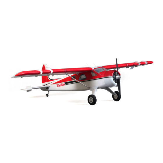
- Page 1 2000mm Beaver V2 Instruction Manual Bedienungsanleitung Manuel d’utilisation 操作手册 FMSMODEL.COM SIMPLE FLOATS RIGID Simple assembly Optional floats Strong durable EPO...
- Page 2 WARNING WARNING: Read the ENTIRE instruction manual to become familiar with the features of the product before operating. Failure to operate the product correctly can result in damage to the product,personal property and cause serious injury. This is a sophisticated hobby product and NOT a toy. It must be operated with caution and common sense and failure to do so could result in injury or damage to the product or other property.
-
Page 3: Table Of Contents
FMS 2000mm Beaver V2 Official release notes! • Hollowed wing design reduces flying weight The FMS 2000mm Beaver V2 is a real “pilot’s plane”. Weighing • Metal landing gear withstands the hardest of landings in at just 3800g and having over 5000g of thrust- the Beaver V2 •... -
Page 4: Model Assembly
Model assembly Landing gear set installation 1.Attach the landing gear set to the landing gear slot on the underside of the fuselage. The five screws are installed as shown . Main wing installation 1.Slide the wing spar into the fuselage then install both wings over the wing spar and into the fuselage pass-through of the fuselage. - Page 5 Model assembly 2.Install the 2 wing struts on the fuselage mount using 2 R-clips. HKM3.0*26mm 3. Secure the wing structure onto the fuselage using 4 screws as shown. Ensure that these screws are securely tightened. Horizontal stabilizer installation 1. Slide the horizontal stabilizer spar into the pass through at the rear of the aircraft.
- Page 6 Model assembly 3. Install the 4 included screws to secure the stabilizer halves. Vertical stabilizer installation 1. Connect the rudder and elevator servo connectors to the servo extensions in the fuselage. 2. Slide the vertical tail assembly into slot in the fuselage. CAUTION:DO NOT crush or damage the wiring when attaching the vertical tail assembly to the fuselage.
- Page 7 Model assembly Installation of the vortex generators 1. Carefully apply CA to the indentations located on the leading edge of the wings. 2. Carefully slide the vortex generators onto the indentations as shown. Installation of other scale components 1. Carefully adhere the pitot tube to the leading edge of the wing as shown.
- Page 8 Model assembly 4.Adhere the antenna to the top of the center wing box. Optional glider release hitch installation 1. Install the glider release mechanism to the top of the fuselage and secure with 4 screws as shown. KA2.6x12mm...
- Page 9 Model assembly 2. Install the aerodynamic fairing for the mechanism to the top of the fuselage and secure with two screws. Linkage rod installation 1.With the servo centered, install and adjust the pushrod and clevises. Connect the clevis to the outermost hole on the control horn.
- Page 10 Model assembly Optional float installation 1. Install the struts to both sides of the float. The front strut is longer with 422mm length, the rear strut is shorter with 412mm length. Wrong installation will cause difficulty landing and taking off. 2.Install the float strut to the float with 8 screws as picture shows.
- Page 11 Model assembly 3.With the fuselage bottom facing up, carefully install the float set to the fuselage with 6 screws. 4.Connect the float servo and fuselage connector. Note: black wire to mark "-", yellow wire to mark "s" Propeller installation 1.Assemble the spinner and propeller as shown. Note: the motor should rotate clockwise when viewing the plane from the rear.
-
Page 12: Battery Installation
Battery installation 1. Pull back on the release tab and remove the battery hatch. 2. Apply hook tape to the cable end of the battery. 3. Make sure the battery is secured using hook tape. Note: batteries from different manufacturers will vary in weight and size, it is therefore important to check the center of gravity of the aircraft before every flight. - Page 13 Transmitter and model setup Before getting started, bind your receiver with your transmitter. Bank left Please refer to your transmitter manual for proper operation. CAUTION: To prevent personal injury, DO NOT install the propel- ler assembly onto the motor shaft while testing the control surfac- es.
-
Page 14: Clevis Installation
Clevis installation 1.Pull the tube from the clevis to the linkage. 2.Carefully spread the clevis, then insert the clevis pin into the desired hole in the control horn. 3.Move the tube to hold the clevis on the control horn. Control horn and servo arm settings More control throw Horns Arms... -
Page 15: Before Flying The Model
Before flying the model Flying course Find a suitable flying site Take off While applying power, slowly steer to keep the model straight. Find a flying site clear of buildings, trees, power lines and The model should accelerate quickly. As the model gains flight other obstructions. -
Page 16: Troubleshooting
Trouble shooting Problem Possible Cause Solution Aircraft will not respond to -Lower throttle stick and throttle trim to lowest settings. -ESC is not armed. the throttlebut responds to -Reverse throttle channel on transmitter. -Throttle channel is reversed. other controls. -Damaged spinner, propeller, -Replace damaged parts.
Need help?
Do you have a question about the 2000mm Beaver V2 and is the answer not in the manual?
Questions and answers